Radar Transceiver Module PCBA
Discover high-performance Radar Transceiver Module PCBA solutions engineered for precision detection and ranging. Our advanced assemblies integrate cutting-edge RF circuitry and signal processing to deliver exceptional sensitivity and reliability for automotive, industrial, and IoT applications. Trust our expertise to accelerate your radar system development with robust, ready-to-deploy modules.
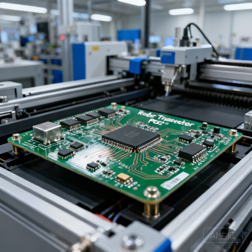
Overview
Radar Transceiver Module PCBA — NovaPCBA's Specialized Service
When a single radar transceiver module PCBA fails in the field, the root cause often traces back to uncontrolled assembly processes or unqualified materials—a risk highlighted by industry data showing that 52% of product recall events stem from exactly these gaps[1]. For RF engineers and procurement managers, yield loss on millimeter-wave boards isn’t just a cost issue; it’s a lead-time and safety risk. NovaPCBA’s specialized service addresses this by combining ISO9001-certified processes, IPC-A-610 Class 2/3 workmanship, and a fully integrated turnkey approach—ensuring that every radar transceiver module PCBA, from the transceiver antenna to the DSP, meets strict RF performance and reliability targets before it leaves our floor.
What's Included in Our Radar Transceiver Module PCBA Service
- RF-optimized SMT & THT hybrid assembly: High-speed pick-and-place for 0201 to large QFN/BGA packages, with through-hole support for connectors and power devices. All processes are tuned for the low-loss laminates (Rogers RO3003, Isola 370HR) typical in radar transceiver module PCBA[2].
- Controlled impedance and low-insertion-loss traces: We verify impedance on 50Ω single-ended and 100Ω differential pairs using TDR measurements, critical for maintaining signal integrity in the 24 GHz, 60 GHz, and 77 GHz bands.
- Thermal management integration: Copper-coin embedding, thermal vias under power amplifiers, and selective heavy-copper plating keep junction temperatures within safe limits, preventing drift in radar transceiver module PCBA performance.
- Full bill-of-materials (BOM) management: We source active RF chipsets, passives, and specialty substrates from franchised distributors, with counterfeit mitigation and lot-level traceability for every component.
- Conformal coating & ruggedization: Parylene, acrylic, or silicone coatings protect against moisture and condensation, essential for outdoor radar sensors and automotive radar transceiver module PCBA.
Industries & Applications
Radar transceiver module PCBA is at the heart of several high-reliability sectors. Automotive ADAS and autonomous driving require IATF 16949-aligned assembly practices for long-range and corner radar modules, where zero-defect soldering under RoHS is non-negotiable. Industrial automation and robotics use millimeter-wave radar for precise distance and velocity sensing in dusty, high-vibration environments; our PCBA withstands thermal cycling from -40°C to +125°C. Aerospace and defense applications demand ITAR-compliant handling and IPC-A-610 Class 3 for altimeters and collision-avoidance radar, where a single solder void can become a field failure. Smart infrastructure and traffic monitoring relies on radar transceiver module PCBA for all-weather object detection; our conformally coated boards ensure long-term reliability without signal attenuation.
Service Model Comparison
| Parameter | In-House Assembly (NovaPCBA) | Offshore-Only | Turnkey (Integrated) |
|---|---|---|---|
| Lead Time | 5–7 days prototype, 2–3 weeks production; no customs delays | 3–4 weeks typical, plus 1–2 weeks shipping/customs[3] | 8–12 weeks with multiple handoffs; engineering changes slow |
| Defect Catch | AOI at every stage + X-ray for BGA/QFN; defects caught before reflow | Often limited to final visual inspection; latent BGA head-in-pillow missed | Responsibility gaps between design, fab, and assembly; 52% recall risk[1] |
| Cost Driver | NRE amortized over volume; no rework hidden costs | Low unit price, but rework, scrap, and travel erode savings | High management overhead; change orders inflate budget |
| Failure Boundary | Full ownership from raw laminate to functional test; single point of accountability | Supplier handoffs create “no-fault-found” loops; root cause unclear[4] | Multiple vendors blame each other; field returns take months to analyze |
Note: Offshore-only models often rely on generic FR-4 processes, ignoring the high-frequency laminate requirements of radar transceiver module PCBA[2]. A turnkey approach with a single partner like NovaPCBA eliminates these gaps, as recommended by leading RF PCB design guides[5].
Our Manufacturing Process
- DFM & material selection: We review Gerber files and BOM for impedance structures, stack-up, and component compatibility, selecting Rogers/Isola laminates and ENIG/immersion silver finishes to minimize insertion loss.
- Solder paste application & SPI: Laser-cut stencils (0.1–0.12 mm) with nano-coating ensure precise paste volume; solder paste inspection (SPI) verifies every pad before placement.
- High-precision SMT placement: Chip shooters and multi-function placers handle 01005 to 45×45 mm BGA packages with ±25 µm accuracy, critical for the dense RF front-end of a radar transceiver module PCBA.
- Reflow & selective wave soldering: Profiled reflow ovens with 10+ zones control ramp rates for mixed-technology boards; selective wave soldering for through-hole connectors avoids thermal shock to sensitive RF ICs.
- Inspection & test: Automated optical inspection (AOI) post-placement and post-reflow catches misalignments, tombstones, and bridging. X-ray verifies BGA/QFN voiding below 25%. In-circuit test (ICT) and functional RF test measure output power, phase noise, and antenna pattern.
Quality Assurance
Every radar transceiver module PCBA is built to IPC-A-610 Class 2 or Class 3 acceptance standards, with AOI at every assembly stage—post-print, post-placement, and post-reflow—catching defects such as insufficient solder, lifted leads, and solder balls before they become field failures. X-ray inspection is mandatory for all area-array packages, ensuring void percentages stay within J-STD-001 limits. In-circuit test verifies component values and polarity, while functional RF testing under temperature cycling confirms that the module meets its specified EIRP and noise figure. Our ISO9001-certified quality management system enforces lot-level traceability from bare PCB to finished assembly, and we provide certificates of conformance (CoC) with every shipment. This layered approach directly addresses the failure analysis challenges documented in industry troubleshooting guides[6], ensuring that no radar transceiver module PCBA leaves our facility with a latent defect.
Frequently Asked Questions
- Q: How can we audit your facility for radar transceiver module PCBA capability?
- A: We welcome on-site and virtual audits. You’ll review our ISO9001:2015 certification, IPC-A-610 training records, RF test equipment calibration logs, and ESD control procedures. We can also arrange a live build of a qualification lot so your engineering team can witness first-pass yield and RF performance.
- Q: What traceability and CoC documentation do you provide with each shipment?
- A: Every radar transceiver module PCBA ships with a detailed Certificate of Conformance that includes the bare PCB lot code, solder paste batch, component date codes, reflow profile snapshot, AOI/X-ray reports, and functional test data. We retain full build records for 10 years, supporting any future failure analysis or regulatory audits.
- Q: What is the typical lead time for Radar Transceiver Module PCBA?
- A: Prototype quantities (5–50 units) typically ship in 5–7 working days after BOM and Gerber approval, assuming all long-lead RF ICs are in stock. Production volumes (500+) run 2–3 weeks, with a fast-track option for critical orders. We also offer consigned inventory programs to reduce lead time risk on allocation-prone components.
Get a Quote for Radar Transceiver Module PCBA
Submit your Gerber files, BOM, and test specifications for a free, no-obligation quote. Our engineering team will review stack-up, impedance requirements, and component availability within 24 hours. Experience fast turnaround, transparent DFM feedback, and the quality commitment that only an ISO9001/IPC-A-610 certified partner can deliver.
References & Further Reading
- Quality and Compliance in End-to-End PCB & PCBA Manufacturing Service in 2026 – Ring PCB
- Millimeter wave radar PCBA - PCB Assembly
- High Quality Speed Radar Equipment Core PCBA Radar Systems Assembly PCB PCBA Manufacturer – Made-in-China
- PCBA Failure Analysis and Solutions | Leadsintec
- Radar PCB Design Guide: Key Considerations for High-Frequency & RF Applications – RayPCB
- Troubleshooting PCBA Nightmares: A Practical Guide for Engineers – ALLPCB
- Radar PCB: A Radio Frequency Circuit for Detection and Automation – OurPCB