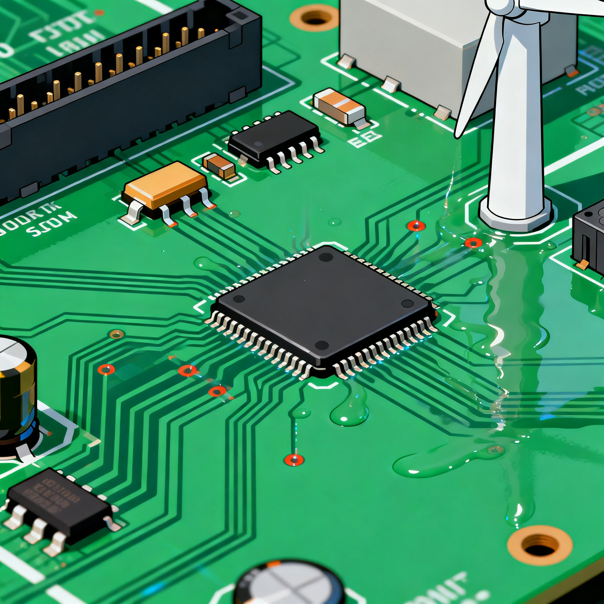
Troubleshooting 5 Common Failures in Wind Turbine Control PCB Assembly: Conformal Coating, Vibration, and Thermal Cycling
Troubleshooting 5 Common Failures in Wind Turbine Control PCB Assembly: Conformal Coating, Vibration, and Thermal Cycling When SCADA False Alarms Mask Real PCB Failures Wind farm operators rely on SCA...
Troubleshooting 5 Common Failures in Wind Turbine Control PCB Assembly: Conformal Coating, Vibration, and Thermal Cycling
When SCADA False Alarms Mask Real PCB Failures
Wind farm operators rely on SCADA data to schedule maintenance and predict failures, but the system itself can be a source of confusion. A SCADA communications hiccup can trigger a 4% false alarm rate, while sensor drift—especially from anemometer calibration errors—silently degrades power curve accuracy by up to 11% (wifitalents). When control boards misinterpret wind speed or direction, pitch and yaw actuators respond incorrectly, loading blades and drivetrain components in ways that accelerate mechanical wear. The result is a cascade: what looks like a gearbox or bearing problem often traces back to an electrical root cause on a printed circuit board inside the nacelle.
Most of these issues begin with small surface defects that grow over time (gridinta). A micro-crack in a conformal coating, a cold solder joint on a DSP, or a via barrel weakened by thermal cycling can introduce intermittent faults that SCADA either misses or misclassifies as a communication timeout. Mechanical failures—rotor blade erosion, gearbox pitting, main shaft fatigue—are well documented, but the underlying electrical triggers are often overlooked (Springer). Poor connections and control system faults, including arcing and short circuits, can spread damage far beyond the PCB itself (industryleaders). That’s why printed circuit boards are now considered the critical component to monitor in any reliability-centered maintenance program (Windurance).
For the PCB assembly engineer or the sourcing manager, the takeaway is clear: you cannot trust SCADA alone to flag control board degradation. By the time a pitch control PCB throws a hard fault, the conformal coating may have been breached for months, and vibration fatigue may have already cracked multiple BGA balls. The next section maps exactly how these silent killers operate and what failure signatures to look for before the turbine trips.
The Three Silent Killers: Conformal Coating Breaches, Vibration Fatigue, and Thermal Cycling
Wind turbine control PCBs live in an environment that combines salt mist, extreme temperature swings, and continuous low-frequency vibration. Three failure mechanisms dominate field returns, and they often interact in ways that accelerate damage. Understanding each one—and the diagnostic clues it leaves—is the first step toward building boards that survive a 20-year design life.
Conformal coating breaches are the most insidious. A pinhole or a thin spot in acrylic, silicone, or parylene coating allows moisture and airborne contaminants to reach the copper traces. Under DC bias, dendritic growth forms between adjacent conductors, causing intermittent leakage currents that look like sensor drift or communication dropouts. In early stages, the board may recover when the nacelle warms up, fooling remote diagnostics. Once the dendrite bridges two nets, a hard short occurs, often taking down an entire pitch axis.
Vibration fatigue targets solder joints and component leads. The nacelle vibrates at blade-passing frequencies (typically 0.5–2 Hz) and gearbox mesh harmonics that can reach hundreds of Hz. Large surface-mount components like transformers, capacitors, and BGAs act as inertial masses, concentrating stress on their solder connections. Over millions of cycles, solder grain boundaries coarsen and cracks propagate, eventually causing open circuits. The failure signature is often a “no fault found” board that works on the bench but fails when the turbine reaches a specific RPM band—classic resonant excitation.
Thermal cycling is relentless. A turbine in the North Sea can see ambient swings from -20°C to +40°C in a single day, while internal electronics heat up further during operation. The CTE mismatch between FR-4 laminate (14–16 ppm/°C) and ceramic chip components (6–8 ppm/°C) shears solder joints; the z-axis expansion of the PCB (50–70 ppm/°C) stresses copper plating inside vias, eventually cracking the barrel. Delamination between resin and glass fibers creates paths for moisture, compounding coating breaches (mclpcb).
The table below maps common field symptoms to the most likely root causes, helping you triage returned boards before destructive analysis begins.
| Failure Signature | Most Likely Root Cause | Physical Mechanism |
|---|---|---|
| Intermittent I/O, random resets | Conformal coating breach | Moisture ingress → dendritic growth → leakage currents |
| Ground shifts, analog drift | Coating pinhole near analog front-end | Corrosion under coating changes trace impedance |
| Communication dropouts at specific RPM | Vibration-induced BGA crack | Solder joint fatigue at resonant frequency |
| Board works cold, fails hot | Via barrel crack | Z-axis CTE mismatch opens via under thermal expansion |
| Complete loss of pitch axis | Dendritic short across power planes | Conformal coating breach + contamination + DC bias |
| High-resistance joints after 3–5 years | Solder creep / grain coarsening | Thermal cycling + vibration synergy |
These failure modes rarely appear in isolation. A via crack that lets moisture into the inner layers will accelerate CAF (conductive anodic filament) growth, while vibration can turn a partially delaminated pad into a lifted land. When you receive a field-returned board that exhibits multiple symptoms, assume that all three killers have been at work. The diagnostic table above helps you prioritize which root cause to attack first, but the real solution lies in the protection strategy you choose at the design stage.
Conformal Coating vs. Potting vs. Ruggedized Layout: Which Defense Fits Your Control PCB?
There is no single “best” protection method for a wind turbine control board; the right choice depends on the board’s location in the nacelle, the expected service life, and the repair philosophy of the operator. Offshore turbines governed by IEC 61400-3-1 demand higher resilience against salt spray and condensation, while onshore machines in desert climates battle dust and extreme diurnal temperature shifts (ANSI). The comparison below evaluates five strategies across the metrics that matter most for long-term reliability.
| Protection Strategy | Moisture & Corrosion Resistance | Vibration Damping | Reworkability | Typical Application |
|---|---|---|---|---|
| Acrylic conformal coating (AR) | Good; easy to inspect under UV | Minimal | Easy—solder-through possible | Onshore pitch control, yaw drives |
| Silicone conformal coating (SR) | Excellent; remains flexible at -40°C | Moderate—dampens high-frequency vibration | Difficult; requires mechanical removal | Offshore nacelle electronics, humid environments |
| Parylene (XY) vapor-deposited coating | Superior; pinhole-free at 25 µm | Low | Very difficult; must be abraded off | High-density boards with fine-pitch components, offshore |
| Full potting (polyurethane or epoxy) | Complete encapsulation | Excellent—mass loading shifts resonant frequencies | Impossible; board is a throwaway | Condition monitoring sensors, slip ring assemblies |
| Ruggedized layout (no coating) | Depends on enclosure IP rating | Relies on underfill, staking, and connector locks | Full rework access | Sealed cabinets with active climate control |
Acrylic coatings are the workhorse for onshore turbines because they are inexpensive, easy to apply, and glow under UV light, making inspection straightforward. However, acrylic becomes brittle at low temperatures and offers almost no vibration damping. Silicone coatings stay flexible down to -40°C and provide some mechanical damping, but they are nearly impossible to rework without damaging pads. Parylene delivers a truly conformal, pinhole-free barrier at just 25 µm thickness, ideal for dense mixed-signal boards where clearance is tight. Its downside is zero reworkability—any repair requires abrasive removal and re-coating in a vacuum chamber. Potting solves both moisture and vibration problems in one step, but it turns the PCB into a non-serviceable assembly. If your maintenance strategy leans toward board replacement rather than repair, potting is a valid choice; if you need to swap a failed op-amp in the field, avoid it (Windurance). Ruggedized layout without coating is only viable inside hermetically sealed enclosures with active heaters or desiccants—a rare luxury in most nacelles.
The decision often comes down to a trade-off between upfront manufacturing cost and lifecycle reliability. A parylene-coated board may cost 30–50% more than an acrylic-coated equivalent, but if it prevents a single unscheduled maintenance trip to an offshore turbine, the ROI is immediate. The next section details the design and sourcing practices that make any of these protection strategies work reliably.
Design and Sourcing Moves That Stop Control PCB Failures Before They Start
Even the best conformal coating cannot save a board that was designed with sharp corners, inadequate clearances, or the wrong laminate. Wind turbine control PCBs demand a set of design rules that go well beyond commercial IPC Class 2. The following practices have been distilled from field failure analyses and reliability testing programs across multiple turbine platforms.
Start with IPC Class 3 acceptance criteria. Class 3 mandates tighter annular ring requirements, minimum solder fillet heights, and stricter void limits for BGAs. These rules directly combat vibration fatigue and thermal cycling damage. For pitch and yaw control boards, specify Class 3 in your fabrication and assembly drawings, and verify that your contract manufacturer has recent experience with high-reliability laminates like polyimide or high-Tg FR-4 (Tg ≥ 170°C).
Design for coating coverage. Keep components at least 2 mm away from board edges to allow a continuous coating meniscus. Avoid tall components that shadow adjacent low-profile parts; if unavoidable, specify a two-coat process or use a selective coating robot with tilt capability. Define keep-out zones around connectors and test points that will be masked, and call out these areas explicitly in the coating drawing.
Control CTE mismatches. For boards that will experience more than 1,000 thermal cycles per year, consider using a laminate with a lower z-axis CTE, such as Isola 370HR or Panasonic Megtron 6. These materials reduce via barrel stress and extend plated-through-hole life. Pair them with underfill on large BGAs and corner staking on tall capacitors to shift resonant frequencies above the nacelle vibration spectrum.
Align lead times with turbine assembly schedules. Wind turbine manufacturing operates on tight project timelines. A control PCB that arrives late can trigger expedited shipping fees that dwarf the board cost itself. Work with your EMS partner to lock in material lead times for critical components—especially FPGAs, isolated gate drivers, and high-voltage connectors—and build buffer stock for long-lead items (aivon).
Validate with the right test protocols. The table below summarizes the minimum testing every wind turbine control PCB should pass before deployment. These tests are not optional; they are the gatekeepers that catch coating breaches, weak solder joints, and marginal laminates before they become field failures.
| Test | Standard / Guideline | Parameters | What It Catches |
|---|---|---|---|
| Thermal cycling | IPC-TM-650 2.6.7.1 | -40°C to +85°C, 1,000 cycles, dwell ≥ 15 min | Via barrel cracks, delamination, solder joint fatigue |
| Random vibration | IEC 61400-3-1 / MIL-STD-810 | 5–500 Hz, 2–5 gRMS, 3 axes, 1 hr/axis | Resonant solder joint cracks, connector fretting |
| Conformal coating inspection | IPC-CC-830 / UV AOI | 100% AOI under UV, ionic contamination < 1.56 µg/cm² NaCl | Pinholes, thin spots, contamination under coating |
| Insulation resistance (SIR) | IPC-TM-650 2.6.3.3 | 85°C / 85% RH, 100 VDC bias, 168 hours | Dendritic growth, CAF, coating porosity |
| HALT (Highly Accelerated Life Test) | Internal spec based on UFGS 48 15 00 | Combined thermal + vibration step stress to failure | Design margin weaknesses, component infant mortality |
The UFGS 48 15 00 specification provides additional environmental design margins for wind generator systems, including salt fog exposure and operational temperature extremes that can be used to tailor the HALT profile (wbdg). Many turbine OEMs also maintain their own technical documents that define acceptance criteria for control electronics; accessing these through repositories like the MWPS wind turbine document index can help you align your test plan with the end customer’s expectations (MWPS).
Tip: When qualifying a new PCB assembly partner, ask for a failure analysis report from a previous wind turbine program. A supplier who can walk you through a cross-section of a failed via or a SAM image of a delaminated board demonstrates the diagnostic depth you need when things go wrong.
Wind Turbine Control PCB Failure FAQs: What Senior Engineers and Buyers Ask
Q: How can I detect conformal coating pinholes before field deployment?
A: Automated optical inspection (AOI) with UV light is the first line of defense. Most coatings fluoresce under UV, and modern AOI systems can flag areas where the coating is too thin or missing. Follow up with ionic contamination testing (ROSE test) to detect residues that indicate a breach. Even a pinhole invisible to the naked eye can grow into a corrosion site after a few hundred thermal cycles (gridinta). For mission-critical boards, add a sample-based SIR test at 85°C/85% RH to confirm the coating’s long-term barrier performance.
Q: What vibration profile should I use for accelerated life testing of a pitch control PCB?
A: Use a swept-sine and random vibration profile derived from actual nacelle measurements. A typical starting point is 5–500 Hz, 2–5 gRMS, with dwells at blade-passing frequencies (0.5–2 Hz) and gearbox mesh harmonics. The IEC 61400-3-1 standard provides guidance for offshore turbines, but even onshore machines benefit from a similar profile (ANSI). Always instrument the board with accelerometers during testing to identify resonant modes; if a component’s natural frequency falls within the excitation band, add staking or underfill to shift it.
Q: Is potting a better long-term solution than conformal coating for offshore turbines?
A: Potting offers superior moisture and vibration protection because it completely encapsulates the board, eliminating air gaps where condensation can form. However, it makes the PCB non-repairable. If your maintenance strategy is to replace the entire board at failure, potting is an excellent choice. If you need to perform field repairs—swapping a damaged connector or a failed sensor interface—parylene coating provides a thin, pinhole-free barrier that can be locally removed and re-applied, albeit with specialized equipment. The decision hinges on your repair philosophy and the cost of downtime (Windurance).
Q: How can I ensure my PCB assembly partner understands wind turbine reliability requirements?
A: Require IPC-A-610 Class 3 acceptance as a baseline, and ask for evidence of thermal cycle testing per IPC-TM-650 on similar high-reliability laminates. The partner should have experience with conformal coating application and inspection, and should be able to provide ionic contamination data for every batch. From a supply chain perspective, align lead times with turbine assembly schedules to avoid costly expedited fees; a partner who proactively manages long-lead components like isolated DC-DC converters and fiber-optic transceivers will save you more than a few cents per board (aivon).
Q: What are the most common failure analysis techniques for returned control PCBs?
A: Start with X-ray inspection to check for BGA solder joint cracks, especially under large ASICs and FPGAs. Cross-sectioning is essential for evaluating via barrel integrity and plating thickness; look for barrel cracks that align with the laminate weave. Scanning acoustic microscopy (SAM) can detect delamination at the laminate-resin interface and between the coating and the board surface. These techniques are standard for high-reliability PCB failure analysis and can pinpoint the root cause within hours (mclpcb).
References & Further Reading
- 110+ Wind Turbine Failure Statistics | 2026 Data Report
- Unveiling Wind Turbine Failures Causes, Detection, and Prevention for Enhanced Reliability | Journal of Failure Analysis and Prevention
- Most Common Failures in Wind Turbines & How to Avoid them
- Understanding the Common Causes of Wind Turbine Operational Failures
- Wind Turbine Control PCB Cost Optimization: Strategies for Efficient Manufacturing
- PCB Issue Guide: PCB Failure Analysis and Common Issues
- Wind Turbine Component Replacement vs. Wind Turbine Repair - Windurance
- Wind Turbine Standards
- UFGS 48 15 00 Wind Generator System
- Wind Turbines Technical Documents - Download PDFs • by MWPS
When you need a PCB assembly partner that understands the extreme demands of wind turbine control electronics, NovaPCBA brings 15+ years of high-reliability manufacturing experience to your program. From IPC Class 3 fabrication and conformal coating application to full thermal cycling and vibration validation, we build boards that survive the nacelle. Explore our wind energy PCB assembly capabilities and let’s discuss how to harden your next control board against the three silent killers.