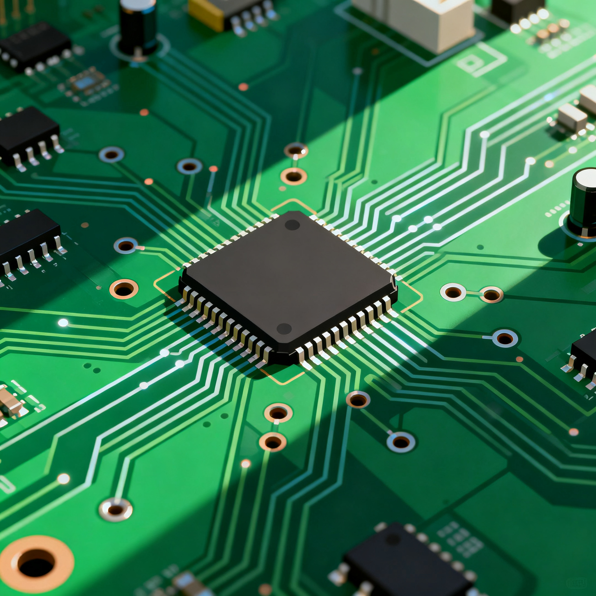
Top High-Speed PCB Routing Practices: Real-World Examples and Tips
Top High-Speed PCB Routing Practices: Real-World Examples and Tips Introduction In today's fast-paced technological landscape, the demand for high-speed electronic devices is ever-increasing. At the h...
Introduction
In today's fast-paced technological landscape, the demand for high-speed electronic devices is ever-increasing. At the heart of these devices lies the printed circuit board (PCB), a critical component that determines the overall performance and reliability of the system. High-speed PCB routing is an essential aspect of PCB design that ensures signal integrity, minimizes electromagnetic interference (EMI), and optimizes power distribution. Understanding and implementing effective high-speed PCB routing practices are crucial for engineers to meet the stringent requirements of modern electronic applications.
Technical Overview
High-speed PCB routing involves the strategic placement and interconnection of components on a PCB to facilitate efficient signal transmission. Key concepts in high-speed PCB routing include controlled impedance, differential pair routing, and signal integrity. Controlled impedance ensures that the signal traces maintain a consistent characteristic impedance, minimizing signal reflections and losses. Differential pair routing involves the use of two complementary signal lines to reduce noise and improve signal quality. Signal integrity encompasses various factors such as crosstalk, ringing, and timing, which can affect the performance of high-speed circuits.
The architecture of a high-speed PCB comprises multiple signal layers, power planes, and ground planes, each serving a specific function. Signal layers carry the electrical signals between components, while power and ground planes provide stable voltage references and reduce EMI. The principles of high-speed PCB routing are governed by industry standards such as IPC-2221 and IPC-A-610, which outline guidelines for design, manufacturing, and inspection.
Detailed Specifications
When selecting components for high-speed PCBs, it is essential to consider their specifications to ensure compatibility and optimal performance. Key specifications include CPU speed, memory capacity, peripheral interfaces, power requirements, and package type. These specifications determine the processing capabilities, data storage, and connectivity options of the PCB, directly impacting its functionality and application.
| Specification | Detail | Importance |
|---|---|---|
| CPU Speed | 1.8 GHz | Determines processing power |
| Memory | 8 GB DDR4 | Influences data handling capacity |
| Peripherals | USB 3.0, HDMI | Connectivity options |
| Power Supply | 5V DC | Power requirements |
| Package Type | LGA | Physical layout and assembly |
| Operating Temperature | -40 to 85°C | Environmental tolerance |
| Storage Capacity | 256 GB | Data storage capability |
| Interface | SPI, I2C | Communication protocols |
| Clock Speed | 400 MHz | Signal frequency |
| Dimensions | 100mm x 100mm | Physical size |
Key Takeaways from the Specifications
The specifications outlined in Table 1 provide critical insights into the capabilities and limitations of the components used in high-speed PCBs. The CPU speed and memory capacity are pivotal for determining the processing power and data handling ability of the system. Peripheral interfaces such as USB 3.0 and HDMI offer a wide range of connectivity options, crucial for advanced applications. The power supply requirements and package type influence the design and assembly process, ensuring compatibility with the overall system architecture. Understanding these specifications helps engineers select the right components that meet the specific needs of their applications.
| Characteristic | Specification | Significance |
|---|---|---|
| Operating Voltage | 3.3V | Power efficiency and compatibility |
| Max Current | 2A | Load capacity |
| Input Impedance | 50 Ohms | Signal integrity |
| Output Impedance | 75 Ohms | Transmission quality |
| Propagation Delay | 2 ns | Timing accuracy |
| Rise Time | 0.5 ns | Signal transition speed |
| Fall Time | 0.5 ns | Signal transition speed |
| ESD Protection | ±15kV | Electrostatic discharge safety |
| Thermal Resistance | 35°C/W | Heat dissipation |
| Junction Temperature | 150°C | Operational reliability |
| Storage Temperature | -65 to 150°C | Environmental tolerance |
Practical Implications
The electrical characteristics detailed in Table 2 are crucial for ensuring the performance and reliability of high-speed PCBs. Operating voltage and maximum current define the power and load-handling capabilities, influencing the overall efficiency of the circuit. Impedance values are vital for maintaining signal integrity, essential for high-speed data transmission. Propagation delay and rise/fall times affect the timing accuracy and speed of signal transitions, impacting the synchronization of the system. Understanding these characteristics allows engineers to optimize the design for specific applications, ensuring robust performance under various conditions.
| Application | Configuration | Benefits |
|---|---|---|
| Consumer Electronics | Dual-Layer PCB | Cost-effective, compact design |
| Automotive Systems | Multi-Layer PCB | Enhanced reliability, EMI reduction |
| Industrial Automation | High-Temperature PCB | Durability under extreme conditions |
| Telecommunications | High-Frequency PCB | Improved signal integrity |
| Medical Devices | Flexible PCB | Conformability to complex shapes |
| Aerospace Applications | Rigid-Flex PCB | Weight reduction, space optimization |
| Networking Equipment | High-Density Interconnect PCB | Increased circuit density |
Application Guidelines
Table 3 illustrates the diverse applications of high-speed PCBs and the configurations best suited for each use case. In consumer electronics, dual-layer PCBs offer a balance between cost and compactness, making them ideal for devices like smartphones and tablets. Automotive systems benefit from multi-layer PCBs, which provide enhanced reliability and reduced EMI, critical for safety systems. Industrial automation applications require high-temperature PCBs to withstand extreme conditions, ensuring durability and longevity. Understanding these configurations helps engineers select the appropriate PCB type, optimizing performance and efficiency for specific applications.
Design Considerations
When designing high-speed PCBs, several critical considerations must be taken into account to ensure optimal performance and reliability. First, controlled impedance is essential for maintaining signal integrity. This involves selecting the appropriate trace width and spacing, as well as the dielectric material, to achieve the desired impedance. Differential pair routing is also crucial, as it helps reduce noise and crosstalk by using two complementary signal lines for data transmission.
Another important consideration is the placement of components. Strategic placement minimizes signal path lengths, reducing the risk of signal degradation and timing issues. Additionally, the use of ground and power planes is vital for providing stable voltage references, minimizing EMI, and improving thermal management.
Thermal management is a key aspect of high-speed PCB design. Proper heat dissipation is necessary to prevent overheating and ensure reliable operation. This can be achieved through the use of thermal vias, heat sinks, and appropriate PCB materials with good thermal conductivity.
Finally, signal integrity analysis and simulation tools are invaluable for identifying potential issues and optimizing the design. These tools allow engineers to model and analyze the electrical behavior of the PCB, ensuring that it meets the required performance specifications.
Step-by-Step Implementation
- Define Requirements: Begin by clearly defining the requirements and specifications for the high-speed PCB, including signal frequencies, power levels, and environmental conditions.
- Select Components: Choose components that meet the defined specifications, paying attention to factors such as CPU speed, memory capacity, and peripheral interfaces.
- Design Schematic: Create a detailed schematic that outlines the interconnections between components, ensuring that signal paths are optimized for high-speed operation.
- Layout Design: Use PCB design software to create the layout, focusing on controlled impedance, differential pair routing, and strategic component placement.
- Signal Integrity Analysis: Perform signal integrity analysis to identify potential issues such as crosstalk, reflections, and timing errors. Make necessary adjustments to the design.
- Thermal Management: Incorporate thermal management solutions such as heat sinks and thermal vias to ensure adequate heat dissipation.
- Prototype and Test: Manufacture a prototype of the PCB and conduct thorough testing to verify performance and identify any issues.
- Iterate and Optimize: Based on test results, make necessary design adjustments and optimizations, then repeat the testing process until the desired performance is achieved.
Common Issues & Solutions
- Signal Crosstalk: Use differential pair routing and increase the spacing between signal traces to reduce crosstalk.
- Impedance Mismatch: Adjust trace width and spacing, and select appropriate dielectric materials to achieve controlled impedance.
- Excessive EMI: Implement ground and power planes, and use shielding techniques to minimize electromagnetic interference.
- Overheating: Incorporate thermal vias and heat sinks to enhance heat dissipation and prevent overheating.
- Timing Errors: Optimize signal path lengths and use signal integrity analysis tools to identify and correct timing errors.
- Component Placement: Ensure strategic placement of components to minimize signal path lengths and reduce the risk of signal degradation.
Applications & Use Cases
High-speed PCBs find applications in a wide range of industries, each with its unique requirements and challenges. In the telecommunications sector, high-frequency PCBs are essential for maintaining signal integrity in networking equipment. Automotive systems rely on multi-layer PCBs for enhanced reliability and reduced EMI, critical for safety systems. In the medical field, flexible PCBs are used in devices that require conformability to complex shapes. Aerospace applications benefit from rigid-flex PCBs, which offer weight reduction and space optimization. Understanding these use cases helps engineers design PCBs that meet the specific needs of each industry.
Selection & Sourcing Guide
When selecting and sourcing components for high-speed PCBs, it is important to consider factors such as availability, cost, and compatibility with the overall design. Online platforms like IC Online provide a wide range of components, datasheets, and technical resources to assist engineers in making informed decisions. It is also advisable to work closely with suppliers and manufacturers to ensure that the selected components meet the required specifications and quality standards.
FAQ
- What is controlled impedance? Controlled impedance refers to the consistent characteristic impedance of a trace, crucial for maintaining signal integrity in high-speed PCBs.
- Why is differential pair routing important? Differential pair routing reduces noise and crosstalk by using two complementary signal lines, improving signal quality.
- How do I minimize EMI in high-speed PCBs? Implement ground and power planes, use shielding techniques, and optimize component placement to reduce EMI.
- What tools are used for signal integrity analysis? Signal integrity analysis tools such as SPICE simulators and EM field solvers are used to model and optimize PCB designs.
- How can I ensure proper thermal management? Use thermal vias, heat sinks, and materials with good thermal conductivity to enhance heat dissipation.
- What are the benefits of multi-layer PCBs? Multi-layer PCBs offer enhanced reliability, reduced EMI, and increased circuit density, making them ideal for complex applications.
- Can I use flexible PCBs in high-speed applications? Yes, flexible PCBs are suitable for applications requiring conformability to complex shapes and can be designed for high-speed operation.
- What is the significance of signal integrity in high-speed PCBs? Signal integrity ensures that signals are transmitted accurately and reliably, preventing data loss and errors.
- How do I select the right components for my PCB? Consider specifications such as CPU speed, memory capacity, and peripheral interfaces, and consult datasheets for detailed information.
- Where can I find reliable PCB manufacturers? Online platforms like PCBWay and Nova PCBA offer professional PCB fabrication and assembly services with flexible options and fast turnaround times.
Conclusion
High-speed PCB routing is a critical aspect of modern electronic design, requiring a thorough understanding of core specifications, electrical characteristics, and application requirements. By following best practices and leveraging industry standards, engineers can design PCBs that meet the demanding performance and reliability requirements of today's technology-driven world. Through careful component selection, strategic design, and rigorous testing, high-speed PCBs can be optimized for a wide range of applications, ensuring successful implementation and operation.