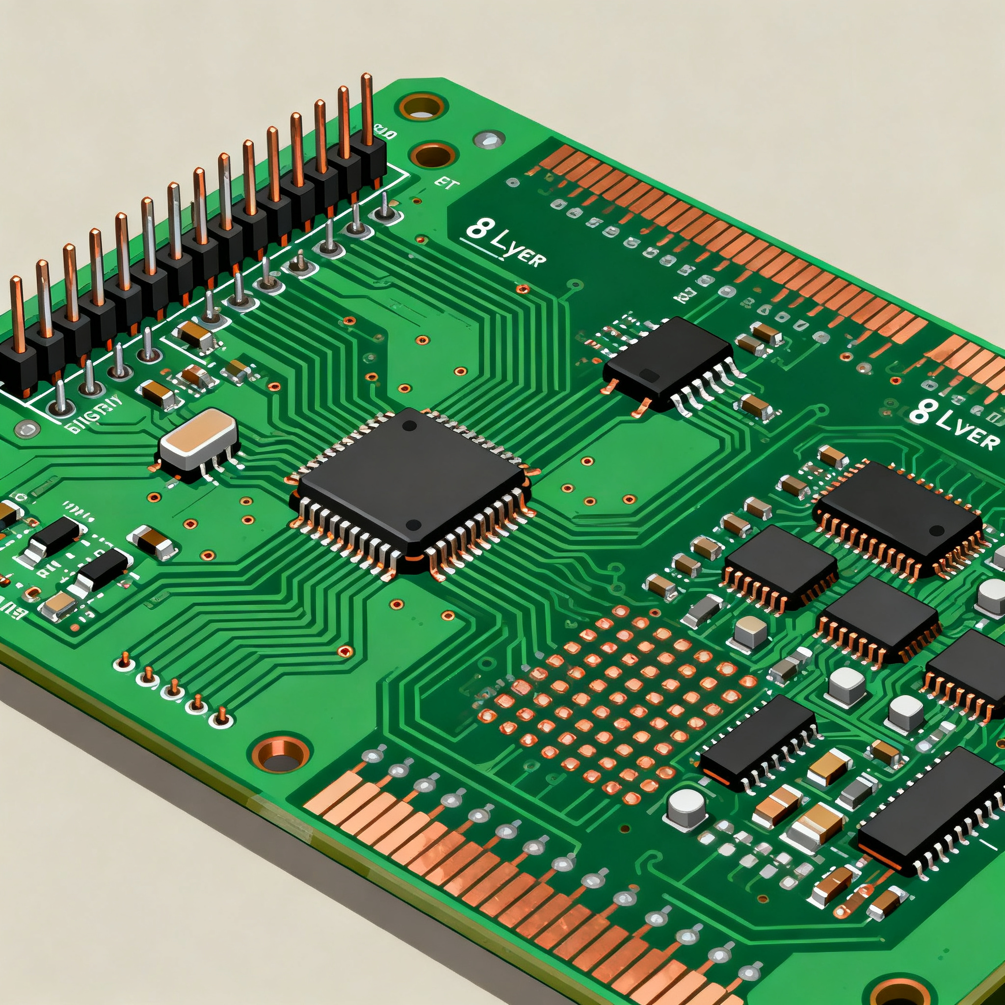
Through-Hole vs Surface Mount: Choosing the Right Technology for Your High-Density 8-Layer PCB
Through-Hole vs Surface Mount: Choosing the Right Technology for Your High-Density 8-Layer PCB Introduction In the evolving landscape of electronics, the choice between through-hole and surface mount ...
Introduction
In the evolving landscape of electronics, the choice between through-hole and surface mount technology (SMT) for high-density, multi-layer printed circuit boards (PCBs) is critical. With the increasing demand for compact yet powerful electronic devices, engineers are challenged to select the optimal technology for their designs. This decision impacts not only the performance and reliability of the final product but also its manufacturability and cost. Understanding the nuances of each technology and how they apply to an 8-layer PCB design is essential for achieving the best results.
Technical Overview
Through-hole technology involves inserting component leads through pre-drilled holes on a PCB and soldering them on the opposite side. This method offers strong mechanical bonds, making it suitable for components that endure mechanical stress. In contrast, surface mount technology involves placing components directly onto the PCB surface without drilling holes. SMT supports higher component density and allows for more compact designs, which is advantageous for high-density PCBs.
An 8-layer PCB provides multiple layers for routing signals, power, and ground planes. This complexity requires careful consideration of component placement and interconnections. SMT is often preferred for its ability to accommodate smaller components and tighter spacing. However, through-hole components may still be used for specific applications requiring robust connections, such as connectors and large power components.
Both technologies have their advantages and limitations. The choice depends on various factors, including the electrical and thermal performance requirements, manufacturing capabilities, and cost constraints. Understanding these factors is crucial when designing high-density PCBs.
Detailed Specifications
When selecting components for your high-density 8-layer PCB, key specifications such as size, power ratings, and packaging types play a vital role. These parameters determine the suitability of either through-hole or SMT components for your design. Below is a table summarizing the key specifications to consider.
| Parameter | Through-Hole | Surface Mount |
|---|---|---|
| Component Size | Larger, bulkier | Smaller, compact |
| Power Rating | Higher (up to 10W) | Lower (up to 2W) |
| Component Density | Lower | Higher |
| Assembly Cost | Higher | Lower |
| Mechanical Strength | High | Moderate |
| Thermal Performance | Better heat dissipation | Requires thermal management |
| Lead Time | Longer | Shorter |
| Reworkability | Easier | More difficult |
| Pin Count | Lower | Higher |
| Packaging Types | DIP, TO-220 | SOP, QFP, BGA |
| Cost | Higher for small volumes | Cost-effective for large volumes |
Key Takeaways from the Specifications
The data in the table highlights the contrasting features of through-hole and SMT components. Through-hole components, with their larger size and higher power ratings, are ideal for applications requiring robust mechanical connections and superior thermal performance. However, they come with higher assembly costs and lower component density. On the other hand, SMT components, being smaller and more cost-effective for mass production, allow for higher component density, making them suitable for compact designs. However, they require careful thermal management due to their limited heat dissipation capabilities. Understanding these specifications helps in making informed decisions based on the design requirements and production volumes.
| Performance Metric | Through-Hole | Surface Mount |
|---|---|---|
| Thermal Resistance | Lower | Higher |
| Signal Integrity | Good | Excellent |
| Reliability | High | Moderate |
| Frequency Range | Up to 100 MHz | Up to 3 GHz |
| Vibration Sensitivity | Less sensitive | More sensitive |
| Electrical Noise | Higher | Lower |
| Heat Dissipation | Better | Poorer |
| Board Flexibility | Less flexible | More flexible |
| EMI Performance | Moderate | Good |
| Durability | Excellent | Good |
Practical Implications
The performance metrics table underscores the strengths and weaknesses of each technology. Through-hole components exhibit lower thermal resistance and higher reliability, making them suitable for high-power and high-stress applications. Their superior durability and vibration resistance are advantageous for industrial and automotive sectors. Conversely, SMT components excel in signal integrity and frequency range, supporting high-speed and high-frequency applications. Their lower electrical noise and EMI performance are beneficial for sensitive electronic devices. However, designers must address their higher thermal resistance and sensitivity to vibration to ensure optimal performance.
| Application | Through-Hole | Surface Mount |
|---|---|---|
| Power Supplies | Preferred | Limited use |
| Consumer Electronics | Limited use | Preferred |
| Automotive | Preferred | Used with caution |
| Telecommunications | Limited | Preferred |
| Medical Devices | Used with caution | Preferred |
| Industrial Equipment | Preferred | Limited use |
| Aerospace | Limited | Preferred |
| Wearable Technology | Not suitable | Preferred |
Application Guidelines
The application matrix table provides a clear view of where each technology excels. Through-hole technology is preferred in power supplies, automotive, and industrial equipment due to its mechanical strength and heat dissipation capabilities. In contrast, SMT is favored in consumer electronics, telecommunications, and wearable technology for its compactness and ability to support high-density designs. In medical devices and aerospace applications, SMT's precision and low-profile nature are advantageous, although through-hole components may still be used in specific scenarios requiring robust connections.
Design Considerations
When designing an 8-layer PCB, several factors must be considered to optimize the use of through-hole and SMT components. First, the layout should balance component density with thermal management. SMT components allow for higher density but generate more heat, necessitating effective thermal vias and heat sinks. Second, signal integrity is paramount, especially in high-frequency applications. Proper trace routing and impedance matching are crucial to minimize signal loss and crosstalk.
Third, the choice of materials and finishes affects the overall performance and reliability of the PCB. High-quality substrates and surface finishes such as ENIG (Electroless Nickel Immersion Gold) provide excellent corrosion resistance and solderability. Fourth, the assembly process must be carefully planned. SMT requires precise placement and reflow soldering, while through-hole components need wave soldering or selective soldering techniques.
Finally, consider the manufacturing and testing processes. Collaborating with a reputable PCB manufacturer ensures adherence to industry standards, such as those outlined by the IPC. Testing procedures, including automated optical inspection (AOI) and in-circuit testing (ICT), validate the functionality and reliability of the PCB before deployment.
Step-by-Step Implementation
- Define the design requirements, including electrical, thermal, and mechanical specifications.
- Select the appropriate mix of through-hole and SMT components based on the application and design constraints.
- Create a detailed schematic diagram, ensuring proper component placement and interconnections.
- Design the PCB layout, taking into account trace routing, layer stack-up, and thermal management.
- Perform design rule checks (DRC) to verify compliance with manufacturing capabilities and standards.
- Generate the necessary manufacturing files, such as Gerber files and bill of materials (BOM).
- Partner with a reliable PCB manufacturer to fabricate and assemble the PCB.
- Conduct thorough testing, including AOI, ICT, and functional testing, to ensure the PCB meets all performance criteria.
Common Issues & Solutions
- Issue: Poor solder joint quality in SMT components.
Solution: Optimize the reflow soldering profile and ensure proper stencil design for accurate solder paste deposition. - Issue: Signal integrity problems due to improper trace routing.
Solution: Use controlled impedance traces and maintain consistent trace widths and spacing to minimize signal reflections and crosstalk. - Issue: Overheating of SMT components.
Solution: Implement thermal vias, heat sinks, and adequate airflow to dissipate heat effectively. - Issue: Mechanical failure of through-hole components under vibration.
Solution: Use additional mechanical supports, such as brackets or adhesives, to secure components and reduce stress. - Issue: Difficulty in reworking SMT components.
Solution: Use specialized rework stations with precise temperature control and appropriate tools for component removal and replacement. - Issue: High EMI levels affecting circuit performance.
Solution: Implement shielding techniques, such as ground planes and ferrite beads, to reduce electromagnetic interference.
Applications & Use Cases
High-density 8-layer PCBs are utilized in a variety of applications, from consumer electronics to industrial automation. In smartphones, SMT components enable compact designs with high functionality, while through-hole components in power supplies ensure reliability and efficiency. Automotive applications benefit from through-hole technology's robustness, especially in engine control units (ECUs) and anti-lock braking systems (ABS). In telecommunications, SMT supports high-frequency operations in routers and switches. The versatility of these technologies allows engineers to tailor their designs to meet specific application needs, balancing performance, cost, and manufacturability.
Selection & Sourcing Guide
When sourcing components for your high-density PCB, consider using reputable online platforms such as IC Online. They offer a wide range of components, datasheets, and technical support to aid in the selection process. It's essential to cross-reference component specifications with your design requirements and consult manufacturers' datasheets for detailed information on performance and compatibility. Establishing a reliable supply chain ensures timely availability of components and supports efficient production schedules.
FAQ
- What are the main differences between through-hole and SMT components?
Through-hole components have leads that pass through the PCB, offering strong mechanical connections, while SMT components are mounted directly onto the PCB surface, allowing for higher density and smaller designs. - When should I use through-hole technology?
Through-hole technology is ideal for applications requiring high mechanical strength, such as power supplies, automotive systems, and industrial equipment. - What are the benefits of using SMT?
SMT supports compact designs with higher component density, making it suitable for consumer electronics, telecommunications, and high-frequency applications. - How do thermal considerations affect component selection?
SMT components generate more heat due to their compact size, necessitating effective thermal management solutions like thermal vias and heat sinks. - What role does signal integrity play in high-density designs?
Maintaining signal integrity is crucial in high-density PCBs to prevent issues like crosstalk and signal loss, especially in high-speed applications. - How can I ensure reliability in my PCB design?
Adhering to industry standards, conducting thorough testing, and selecting components with proven reliability can enhance the durability and performance of your PCB. - What are the challenges of reworking SMT components?
Reworking SMT components can be challenging due to their small size and sensitivity to heat, requiring specialized tools and techniques. - What are the best practices for EMI management?
Implementing ground planes, using ferrite beads, and proper shielding can help reduce electromagnetic interference in your PCB design. - How do I choose the right PCB manufacturer?
Select a manufacturer with a proven track record, adherence to IPC standards, and the capability to meet your specific design and volume requirements. - What factors should I consider when sourcing components?
Consider component specifications, availability, cost, and compatibility with your design, and source from reputable suppliers to ensure quality and reliability.
Conclusion
Choosing the right technology for your high-density 8-layer PCB is a critical decision that impacts the overall performance and reliability of your electronic device. By understanding the specifications, performance metrics, and application guidelines of through-hole and SMT components, engineers can make informed choices that balance design requirements with manufacturing capabilities. As technology continues to evolve, staying abreast of industry standards and best practices ensures that your PCB designs meet the demands of modern electronic applications.