Through-Hole vs Surface Mount: A Cost Optimization Guide for PCB Assembly
Through-Hole vs Surface Mount: A Cost Optimization Guide for PCB Assembly table { border: 1px solid #ccc; border-collapse: collapse; width: 100%; margin: 20px 0; } th, td { border: 1px solid #ccc; pad...
Introduction
In the realm of electronics manufacturing, the choice between through-hole and surface-mount technology (SMT) for PCB assembly is pivotal. This decision influences not only the cost but also the performance, reliability, and manufacturability of electronic assemblies. As the electronics industry continues to evolve, understanding the nuances between these two assembly methods becomes increasingly important. This guide aims to provide a comprehensive analysis of through-hole and SMT, focusing on cost optimization and application suitability.
Technical Overview
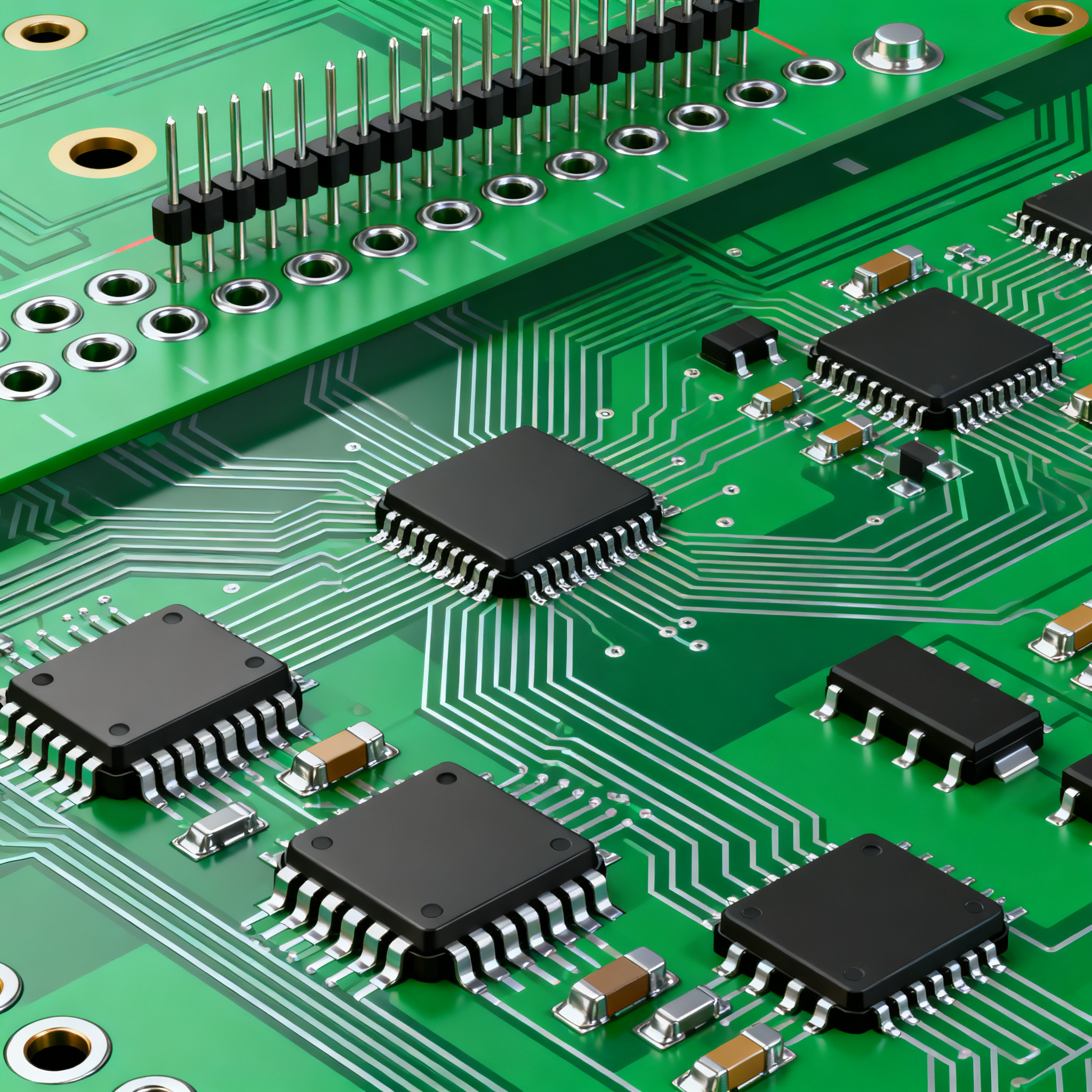
Through-hole technology involves inserting component leads into drilled holes on a PCB and soldering them to pads on the opposite side. It is known for its mechanical strength and is often used in applications where robustness is critical, such as in military or aerospace. On the other hand, surface-mount technology allows components to be mounted directly onto the surface of the PCB. SMT is favored for its ability to support higher component density and its compatibility with automated assembly processes, making it ideal for high-volume production.
The core principles of these technologies hinge on their distinct assembly processes and the resulting implications for design and manufacturing. Through-hole components generally have larger footprints, which can limit the miniaturization of designs. Conversely, SMT components are smaller, enabling more compact and lightweight designs. Understanding these core differences is essential for making informed decisions about PCB assembly, particularly in terms of cost and performance optimization.
Detailed Specifications
When selecting components for PCB assembly, several specifications are crucial. These include electrical parameters such as resistance, capacitance, and inductance, as well as physical dimensions and environmental ratings. Understanding these specifications is vital for ensuring that the chosen components meet the functional and reliability requirements of the end application.
| Parameter | Through-Hole | Surface Mount |
|---|---|---|
| Component Density | Low | High |
| Assembly Speed | Slow | Fast |
| Cost per Unit | High | Low |
| Board Space Utilization | Poor | Excellent |
| Thermal Management | Good | Moderate |
| Vibration Resistance | High | Moderate |
| Repairability | Easy | Difficult |
| Automated Assembly Compatibility | Limited | Excellent |
| Signal Integrity | Good | Excellent |
| Environmental Resistance | High | Moderate |
Key Takeaways from the Specifications
The data in the table highlights the fundamental differences between through-hole and surface-mount technologies. Through-hole components are advantageous in scenarios requiring high mechanical strength and easy repairability, making them suitable for harsh environments. However, they fall short in terms of component density and board space utilization, which can drive up costs in high-volume production. In contrast, SMT components excel in automated assembly and offer better signal integrity, which is crucial for high-frequency applications. This makes SMT the preferred choice for consumer electronics and compact devices.
| Characteristic | Through-Hole | Surface Mount |
|---|---|---|
| Power Dissipation | 1W | 0.5W |
| Operating Temperature | -40°C to 125°C | -40°C to 85°C |
| Thermal Resistance | 20 °C/W | 30 °C/W |
| Electrical Noise | Low | Moderate |
| Current Capacity | 10A | 5A |
| Voltage Rating | 300V | 150V |
| Inductance | High | Low |
| Capacitance | Moderate | High |
| Frequency Response | Good | Excellent |
Practical Implications
Examining the performance metrics, it's clear that through-hole components are better suited for applications requiring higher power dissipation and current capacity. Their superior thermal resistance also makes them ideal for high-power applications. However, SMT components, with their excellent frequency response and lower capacitance, are optimal for high-speed and high-frequency circuits. Designers must weigh these characteristics against the specific needs of their application to achieve the best balance of performance and cost.
| Application | Through-Hole | Surface Mount |
|---|---|---|
| Consumer Electronics | Limited | Extensive |
| Automotive Electronics | Common | Common |
| Industrial Equipment | Common | Common |
| Aerospace and Defense | Preferred | Limited |
| Medical Devices | Preferred | Common |
| Telecommunications | Limited | Extensive |
| Wearable Technology | Not Suitable | Preferred |
| High-Frequency Applications | Limited | Preferred |
Application Guidelines
The application matrix underscores the importance of selecting the right assembly technology based on the intended use case. Through-hole technology is favored in aerospace, defense, and some medical applications due to its robustness and reliability. SMT, however, is indispensable in consumer electronics, telecommunications, and wearable technology, where miniaturization and high-frequency performance are critical. When making a selection, consider the specific environmental and performance requirements of your application to ensure optimal functionality and cost-effectiveness.
Design Considerations
Designing a PCB requires careful consideration of several factors to optimize performance and cost. First, evaluate the physical layout and ensure that the component placement minimizes signal interference and maximizes thermal efficiency. For through-hole designs, ensure that the hole sizes and pad dimensions comply with IPC standards to facilitate assembly and inspection.
For SMT designs, focus on pad design and solder mask definitions to prevent solder bridging and ensure reliable connections. It's also essential to consider the thermal management strategy; SMT components may require additional heat sinks or thermal vias to dissipate heat effectively. Always consult the IPC standards for guidance on design rules and best practices to ensure compliance and manufacturability.
Additionally, consider the trade-offs between component cost and performance. While SMT components generally offer cost savings in high-volume production, the initial setup costs for automated assembly can be significant. Therefore, it's crucial to perform a cost-benefit analysis based on your production volume and application requirements.
Step-by-Step Implementation
- Define the application requirements, including electrical, thermal, and mechanical specifications.
- Select the appropriate assembly technology (through-hole or SMT) based on the application matrix and component availability.
- Design the PCB layout, ensuring compliance with relevant IPC standards and considering factors like signal integrity and thermal management.
- Choose components that meet the specified requirements, referring to datasheets for electrical and thermal characteristics.
- Create a Bill of Materials (BOM) listing all components, their specifications, and suppliers.
- Prototype the PCB design to test functionality and performance, making adjustments as necessary.
- Finalize the design and prepare for mass production, considering cost optimization strategies for assembly and testing.
- Implement quality control measures to ensure the finished product meets all specifications and reliability standards.
Common Issues & Solutions
- Issue: Solder Bridging in SMT Assembly
Solution: Optimize pad design and use appropriate solder paste volume to prevent bridging. - Issue: Poor Thermal Management
Solution: Incorporate thermal vias and heat sinks in the design to dissipate heat effectively. - Issue: Component Misalignment
Solution: Use precise placement equipment and verify alignment during assembly. - Issue: Through-Hole Component Damage
Solution: Ensure proper handling and use of protective packaging during transport and assembly. - Issue: Signal Integrity Issues
Solution: Optimize trace routing and layer stack-up to minimize interference and crosstalk. - Issue: High Production Costs
Solution: Evaluate alternative components and suppliers to reduce material costs and consider redesigns for manufacturability.
Applications & Use Cases
Through-hole and SMT technologies are employed across a wide array of applications. In consumer electronics, SMT is predominant due to its efficiency in automated assembly and compact design requirements. In contrast, through-hole technology is extensively used in industrial settings where durability is paramount. Medical devices often utilize a mix of both technologies, leveraging SMT for compact circuitry and through-hole for critical components requiring robust connections. The telecommunications industry relies heavily on SMT for high-frequency applications, while aerospace and defense sectors favor through-hole for its reliability under extreme conditions.
Selection & Sourcing Guide
Selecting and sourcing components for PCB assembly involves evaluating suppliers based on quality, cost, and delivery reliability. Use resources like IC Online to compare component specifications and pricing. Always ensure that the selected components comply with industry standards and environmental regulations. Consider working with suppliers who offer flexible minimum order quantities and quick turnaround times to accommodate production needs.
FAQ
- Q1: What are the main advantages of SMT over through-hole technology?
A: SMT offers higher component density, faster assembly speeds, and better compatibility with automated processes. - Q2: Can through-hole and SMT components be used on the same PCB?
A: Yes, mixed technology designs are common and can leverage the strengths of both assembly types. - Q3: What factors should I consider when choosing between through-hole and SMT?
A: Consider application requirements, cost, mechanical strength, and production volume. - Q4: How does thermal management differ between through-hole and SMT?
A: Through-hole components typically offer better thermal dissipation; SMT may require additional cooling solutions. - Q5: What are some common challenges with SMT assembly?
A: Challenges include solder bridging, component misalignment, and thermal management. - Q6: Are there cost implications for choosing SMT over through-hole?
A: Yes, SMT can reduce material costs but may involve higher initial setup costs for automated assembly. - Q7: How do I ensure compliance with industry standards in PCB design?
A: Follow IPC standards and guidelines for design, assembly, and quality inspection. - Q8: What role does component selection play in PCB assembly?
A: Component selection is crucial for meeting electrical, thermal, and mechanical requirements while optimizing cost. - Q9: Can SMT components handle high-frequency applications?
A: Yes, SMT components are well-suited for high-frequency applications due to their excellent frequency response. - Q10: What is the impact of environmental factors on component selection?
A: Environmental conditions such as temperature, humidity, and vibration should influence the choice of components to ensure reliability and performance.
Conclusion
Choosing between through-hole and surface-mount technologies for PCB assembly is a critical decision that impacts cost, performance, and reliability. By understanding the specifications, performance metrics, and application guidelines, engineers can make informed decisions that optimize both design and manufacturing processes. Whether the goal is to maximize production efficiency or ensure robust performance in demanding applications, this guide provides a comprehensive framework for navigating the complexities of PCB assembly.