Tackling PCBA Soldering Defects: A Practical Guide to Flawless Connections
Introduction In the rapidly evolving world of electronics, achieving flawless connections on a printed circuit board assembly (PCBA) is crucial for the reliability and performance of electronic device...
Introduction
In the rapidly evolving world of electronics, achieving flawless connections on a printed circuit board assembly (PCBA) is crucial for the reliability and performance of electronic devices. Soldering defects remain a significant challenge in PCBA, often leading to failures in electronic systems. This article delves into the intricacies of tackling PCBA soldering defects, focusing on the specifications and characteristics of integrated circuit (IC) chips. By understanding component specifications, datasheets, selection criteria, and application circuits, engineers can ensure robust and reliable connections.
Technical Overview
The core of any electronic device is its integrated circuits (ICs), which are meticulously designed to perform specific functions. The architecture of ICs includes a combination of transistors, capacitors, and resistors, all encased in a package that facilitates connectivity to a PCB. The principles governing IC design are critical, as they determine the chip's capability to handle tasks efficiently. Understanding the specifications and characteristics of these components is essential for selecting the right IC for your application.
IC chips are characterized by various parameters, including CPU speed, memory capacity, power requirements, and peripheral interfaces. These specifications are crucial for ensuring that the chosen component meets the performance and reliability standards required for the application. Moreover, electrical characteristics such as voltage, current, and I/O specifications play a vital role in determining the compatibility and functionality of the IC within the overall system.
By adhering to industry standards, such as those provided by the IPC, engineers can ensure that their designs meet quality and reliability benchmarks. These standards guide the design, assembly, and inspection processes, helping to minimize defects and enhance the performance of the final product. This article will explore these specifications in detail, providing insights into their significance and practical applications.
Detailed Specifications
Understanding the core specifications of an IC chip is pivotal for ensuring that it meets the functional and performance requirements of a given application. Specifications such as CPU speed, memory, peripherals, and power consumption are critical factors to consider during the selection process. These parameters dictate how the IC will perform under various conditions and influence the overall design of the PCB.
| Specification | Value | Description |
|---|---|---|
| CPU Speed | 1.8 GHz | Processor speed for high-performance computing |
| Memory | 4 GB DDR4 | Volatile memory for data processing |
| Peripherals | USB, I2C, SPI | Interfaces for external device connectivity |
| Power Supply | 3.3V | Operating voltage for the IC |
| Package Type | LQFP | Low-profile quad flat package for compact designs |
| Temperature Range | -40°C to 85°C | Operating temperature range |
| Clock Frequency | 50 MHz | Frequency of the internal clock |
| Data Bus Width | 32-bit | Width of the data bus for data transfer |
| GPIO Pins | 24 | General-purpose input/output pins |
| ADC Channels | 8 | Analog-to-digital converter channels |
| Package Size | 10mm x 10mm | Dimensions of the IC package |
| EEPROM | 128 KB | Non-volatile memory for data storage |
Key Takeaways from the Specifications
The core specifications table provides a comprehensive overview of the critical parameters that define an IC chip's capabilities. CPU speed and memory are fundamental for determining the processing power and data handling capacity of the chip. Peripheral interfaces, such as USB, I2C, and SPI, are essential for ensuring compatibility with other devices and components. The power supply voltage and package type influence the design and integration of the IC into the PCB, while the temperature range and clock frequency are vital for assessing the operating conditions and performance stability. Understanding these specifications allows engineers to select the most suitable IC for their application, ensuring optimal performance and reliability.
| Characteristic | Value | Description |
|---|---|---|
| Operating Voltage | 1.8V to 3.6V | Voltage range for normal operation |
| Maximum Current | 500 mA | Maximum current draw for the IC |
| Input Leakage Current | ±1 μA | Leakage current when inputs are not driven |
| Output High Voltage | 2.8V (min) | Minimum voltage level for a high output |
| Output Low Voltage | 0.4V (max) | Maximum voltage level for a low output |
| Propagation Delay | 5 ns | Time delay from input to output |
| Rise Time | 10 ns | Time for a signal to rise from low to high |
| Fall Time | 10 ns | Time for a signal to fall from high to low |
| ESD Protection | 2 kV | Electrostatic discharge protection level |
| Thermal Resistance | 30°C/W | Junction to ambient thermal resistance |
| Quiescent Current | 5 μA | Current draw when the IC is inactive |
| Power Dissipation | 250 mW | Maximum power dissipation allowed |
Practical Implications
The electrical characteristics table highlights essential parameters that influence the performance and reliability of an IC chip. The operating voltage and maximum current define the power requirements, while input and output voltage levels ensure signal integrity. Propagation delay, rise, and fall times are critical for timing-sensitive applications, impacting the speed at which signals are processed. ESD protection and thermal resistance are vital for safeguarding the IC against environmental hazards and heat dissipation. Understanding these characteristics is crucial for designing circuits that meet performance expectations and operate reliably under specified conditions.
| Application | Configuration | Description |
|---|---|---|
| Embedded Systems | Microcontroller-based | Used in consumer electronics for control and automation |
| Industrial Automation | PLC integration | Control and monitor industrial machinery |
| Automotive | ECU configuration | Engine control units for vehicle management |
| Telecommunications | Signal processing | For data transmission and network management |
| Consumer Electronics | Smart devices | Integration in smartphones and wearable technology |
| Healthcare | Medical devices | Used in diagnostic and monitoring equipment |
| IoT Applications | Wireless modules | Connectivity and data exchange in IoT devices |
| Data Centers | Server optimization | Enhancing performance and energy efficiency in servers |
Application Guidelines
The application comparison table illustrates the diverse use cases and configurations of IC chips across various industries. In embedded systems and consumer electronics, ICs serve as the brain of devices, enabling automation and smart functionalities. Industrial automation and automotive applications leverage ICs for robust control and monitoring capabilities. Telecommunications and data centers utilize ICs for efficient signal processing and server optimization. In healthcare and IoT applications, ICs play a crucial role in enhancing connectivity and device performance. Selecting the right IC configuration for specific applications ensures that the system meets performance, reliability, and efficiency requirements.
Design Considerations
When designing PCBs with IC chips, several considerations are crucial to achieving optimal performance and reliability. First, understanding the thermal management requirements is vital, as excessive heat can degrade performance and reduce the lifespan of the IC. Implementing adequate heat dissipation methods, such as heat sinks or thermal vias, helps maintain a stable operating temperature.
Signal integrity is another critical aspect, especially in high-speed applications. Minimizing signal interference and crosstalk requires careful layout and routing of traces, as well as the use of differential signaling where applicable. Ground planes and decoupling capacitors are essential for reducing noise and ensuring stable power delivery.
Furthermore, selecting the right components based on the IC's specifications and application requirements is crucial. This involves reviewing datasheets and considering factors such as voltage levels, current capacity, and package type. Ensuring compatibility between the IC and other components in the system is key to preventing integration issues.
Finally, adhering to industry standards and best practices, such as those outlined by IPC, ensures that the design meets quality and reliability benchmarks. These standards provide guidelines for PCB design, assembly, and inspection, helping to minimize defects and enhance the overall performance of the final product.
Step-by-Step Implementation
Implementing a successful PCBA with IC chips involves several key steps that ensure the design meets performance and reliability standards. Here is a detailed step-by-step guide:
- Define Requirements: Start by clearly defining the functional and performance requirements of your application. This will guide the selection of the appropriate IC chip and other components.
- Select Components: Based on the defined requirements, select IC chips and other components that meet the necessary specifications. Review datasheets to ensure compatibility and performance.
- Create Schematic: Develop a detailed schematic diagram that outlines the connections and interactions between components. Ensure that the IC is correctly integrated into the design.
- Design PCB Layout: Use PCB design software to create a layout that optimizes trace routing and component placement. Consider factors such as thermal management, signal integrity, and power distribution.
- Simulate Design: Perform simulations to validate the design's performance and identify potential issues. Use simulation tools to analyze signal integrity, thermal behavior, and power distribution.
- Prototype and Test: Fabricate a prototype of the PCB and conduct thorough testing to verify functionality and performance. Identify and address any defects or issues found during testing.
- Iterate and Refine: Based on testing results, refine the design to address any identified issues. Make necessary adjustments to improve performance and reliability.
- Finalize and Manufacture: Once the design is validated and refined, proceed with finalizing the design for mass production. Ensure that manufacturing processes adhere to industry standards and best practices.
By following these steps, engineers can ensure that their PCBA designs with IC chips meet the desired performance, reliability, and quality standards.
Common Issues & Solutions
Despite meticulous design and implementation, soldering defects can still occur in PCBAs. Here are some common issues and solutions:
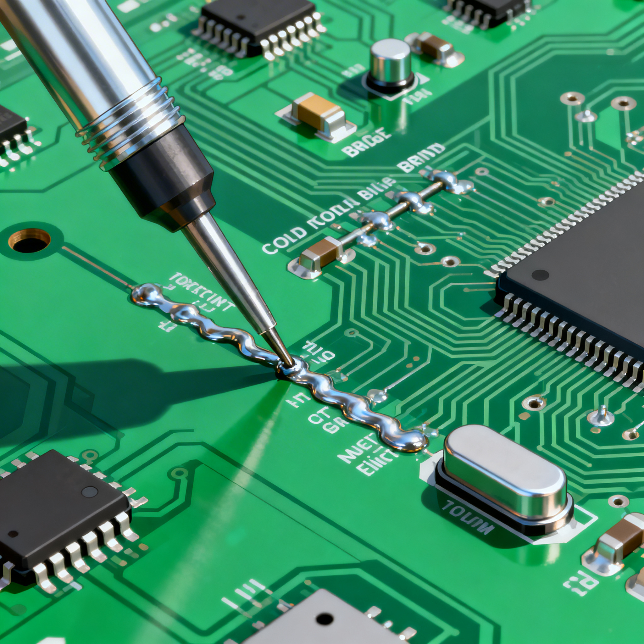
- Cold Solder Joints: These occur when the solder does not properly wet the joint, leading to poor electrical connections. Solution: Ensure proper soldering temperature and time, and use flux to improve wetting.
- Bridging: Solder bridges between adjacent pads can cause short circuits. Solution: Use solder mask to prevent bridging and ensure precise solder paste application.
- Insufficient Solder: Lack of solder can result in weak connections. Solution: Adjust the solder paste stencil thickness and ensure proper solder volume.
- Excessive Solder: Too much solder can lead to bridging or tombstoning. Solution: Optimize solder paste deposition and reflow profiles.
- Component Misalignment: Misaligned components can lead to connectivity issues. Solution: Use automated optical inspection (AOI) to detect and correct misalignment during assembly.
- Voiding: Trapped air in solder joints can weaken connections. Solution: Optimize reflow profiles to minimize voiding and ensure adequate venting.
By addressing these common issues, engineers can improve the quality and reliability of their PCBAs, ensuring robust and flawless connections.
Applications & Use Cases
IC chips are integral to a wide range of applications across various industries. In consumer electronics, they power smartphones, tablets, and wearable devices, enabling advanced functionalities and connectivity. In the automotive industry, ICs are used in engine control units (ECUs) and advanced driver-assistance systems (ADAS), enhancing vehicle performance and safety.
In industrial automation, ICs control machinery and processes, improving efficiency and productivity. Healthcare applications leverage ICs in diagnostic and monitoring equipment, facilitating accurate and timely medical interventions. In telecommunications, ICs enable efficient data transmission and network management, supporting the growing demand for high-speed connectivity.
By selecting the right ICs for specific use cases, engineers can optimize the performance and reliability of their applications, meeting industry-specific requirements and standards.
Selection & Sourcing Guide
When selecting and sourcing IC chips, it's essential to consider factors such as availability, lead time, and cost. Online platforms like IC Online provide a comprehensive database of components, allowing engineers to compare specifications and prices from various suppliers. By leveraging these resources, engineers can make informed decisions and streamline the sourcing process, ensuring that they obtain high-quality components that meet their design requirements.
FAQ
Here are some frequently asked questions related to tackling PCBA soldering defects and IC chip specifications:
- What are the most common soldering defects in PCBAs? Common defects include cold solder joints, bridging, insufficient or excessive solder, component misalignment, and voiding.
- How can I ensure proper soldering temperature and time? Use a temperature-controlled soldering station and follow the recommended soldering profiles provided by the solder paste manufacturer.
- What is the importance of IC chip specifications? Specifications determine the performance, compatibility, and reliability of the IC within an application, guiding the selection process.
- How do I select the right IC for my application? Consider factors such as CPU speed, memory, peripherals, power requirements, and environmental conditions.
- What tools can I use to simulate my PCB design? Simulation tools like SPICE, Altium Designer, and Cadence Allegro can validate design performance and identify potential issues.
- How does ESD protection benefit my design? ESD protection safeguards ICs from electrostatic discharge, preventing damage and ensuring reliability.
- Why is thermal management important in PCB design? Proper thermal management prevents overheating, maintaining performance and extending the lifespan of components.
- What are some best practices for PCB layout design? Use ground planes, minimize trace lengths, and ensure proper spacing to reduce noise and interference.
- How can I prevent component misalignment during assembly? Use automated placement machines and optical inspection to ensure precise alignment.
- What role do industry standards play in PCBA quality? Industry standards provide guidelines for design, assembly, and inspection, ensuring that PCBAs meet quality and reliability benchmarks.
Conclusion
Tackling PCBA soldering defects requires a deep understanding of IC chip specifications, electrical characteristics, and application requirements. By adhering to industry standards and best practices, engineers can design robust and reliable PCBAs that meet performance expectations. Through careful component selection, design considerations, and thorough testing, it's possible to minimize defects and achieve flawless connections, ensuring the success of electronic devices in various applications.