Streamlining Your Project: Best Practices for PCB Manufacturing and Assembly in 2026
Streamlining Your Project: Best Practices for PCB Manufacturing and Assembly in 2026 Introduction As we move toward 2026, the importance of efficient PCB manufacturing and assembly has never been grea...
Introduction
As we move toward 2026, the importance of efficient PCB manufacturing and assembly has never been greater. With the rapid advancement in electronics technology, optimizing the design and production of PCBs is critical for ensuring product quality and market competitiveness. This article delves into the best practices for selecting components, understanding specifications, and applying these in real-world circuits to streamline your projects.
Technical Overview
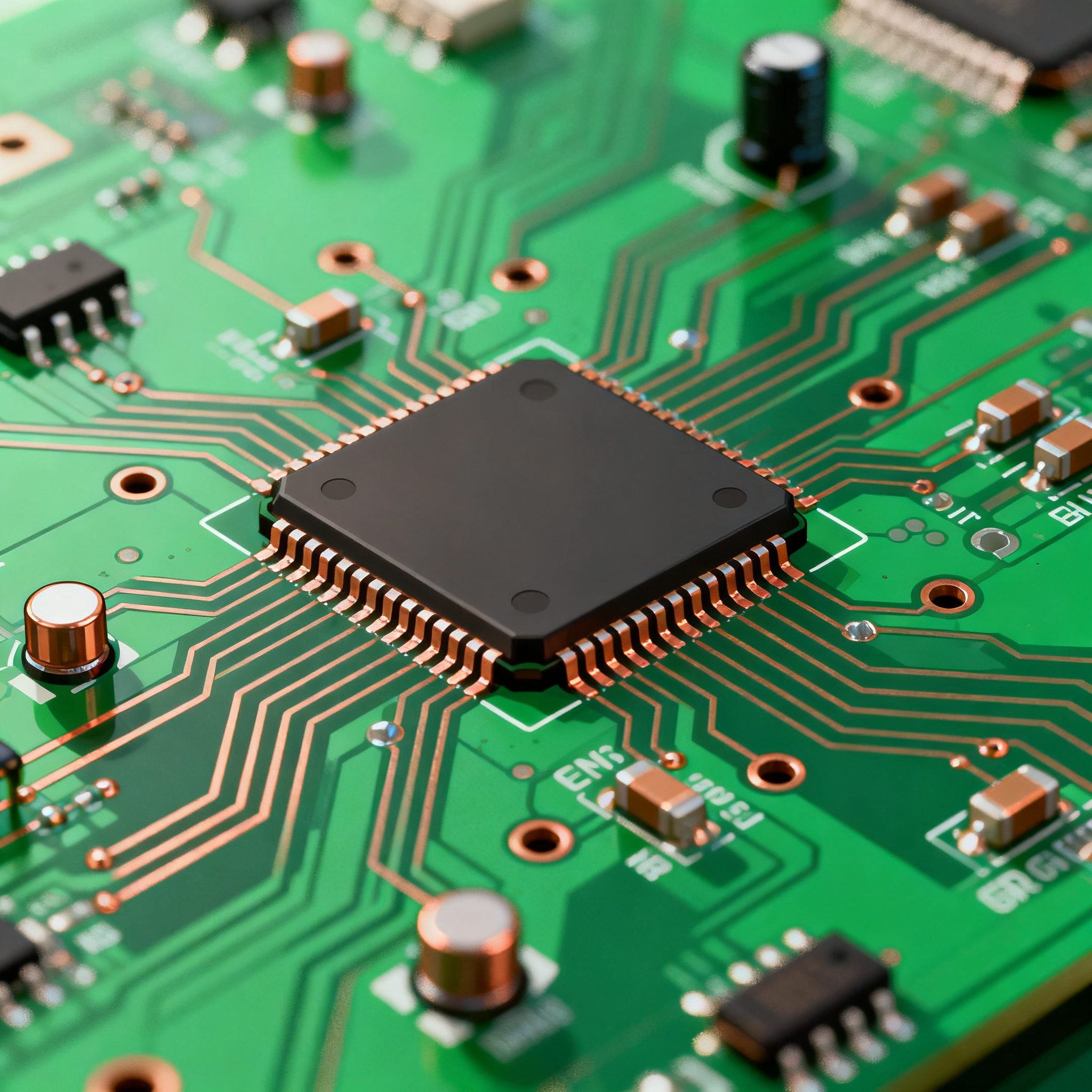
The foundation of any successful electronic project lies in its PCB, which serves as the backbone for all components. The architecture of a PCB involves layers of copper and insulating material that allow for the connection of various components such as IC chips, resistors, and capacitors. Key principles in PCB design include signal integrity, thermal management, and electromagnetic compatibility, all of which are governed by stringent standards such as those set by the IPC.
In the realm of component selection, understanding IC chip specifications is crucial. This includes evaluating CPU speed, memory capacity, peripheral interfaces, power requirements, and package types. The integration of these components must align with the overall design objectives and constraints, ensuring both performance and reliability.
Detailed Specifications
When selecting components for your PCB, it is essential to consider detailed specifications that impact the overall performance and compatibility of your design. These specifications include CPU speed, memory, peripherals, and power requirements, all of which dictate how well the component will perform within the intended application.
| Specification | Details | Notes |
|---|---|---|
| CPU Speed | 2.5 GHz | High performance for complex calculations |
| Memory | 8 GB DDR4 | Efficient data handling |
| Peripherals | USB 3.0, SPI, I2C | Wide range of connectivity options |
| Power Supply | 3.3V, 5V | Standard for most applications |
| Package | LQFP, BGA | Varied form factors for flexibility |
| Temperature Range | -40°C to 85°C | Suitable for industrial use |
| Clock Speed | 100 MHz | Ensures optimal timing |
| Flash Memory | 256 MB | Ample storage for firmware |
| Interface | Ethernet, CAN | Network and automotive applications |
| ADC/DAC | 12-bit resolution | High precision for analog signals |
| Operating Voltage | 1.8V - 3.3V | Low power consumption |
| Packaging | RoHS Compliant | Environmentally friendly |
Key Takeaways from the Specifications
The specifications outlined above are critical in determining the suitability of an IC chip for specific applications. For instance, a CPU speed of 2.5 GHz and 8 GB DDR4 memory ensure high performance, making it ideal for computationally intensive tasks. The variety in peripherals such as USB 3.0, SPI, and I2C allows for extensive connectivity, which is crucial for modern devices requiring multiple interfaces. Additionally, the operating voltage of 1.8V - 3.3V supports low power consumption, aligning with energy-efficient design goals.
| Characteristic | Value | Significance |
|---|---|---|
| Supply Voltage | 1.8V - 5V | Flexibility in power management |
| Input Current | 10 mA | Low power input for efficiency |
| Output Current | 20 mA | Supports various loads |
| Switching Frequency | 500 kHz | High-speed operation |
| Input Capacitance | 15 pF | Affects signal integrity |
| Output Capacitance | 10 pF | Stability in output signals |
| Rise Time | 5 ns | Quick signal transitions |
| Fall Time | 4 ns | Efficient signal processing |
| Input Impedance | 50 Ohms | Minimizes reflection losses |
| Output Impedance | 75 Ohms | Ensures proper load matching |
| ESD Protection | ±2000V | Prevents damage from electrostatic discharge |
| Thermal Resistance | 45°C/W | Heat dissipation capability |
Practical Implications
The electrical characteristics detailed in the table provide essential insights into the operational capabilities of the IC chip. With a supply voltage range of 1.8V to 5V, designers have the flexibility to manage power consumption effectively. The low input current of 10 mA and output current of 20 mA are indicative of efficient energy use, crucial for battery-powered devices. Additionally, the ESD protection rating of ±2000V ensures the chip's resilience against electrostatic discharge, enhancing its reliability in various environments.
| Application | Configuration | Benefits |
|---|---|---|
| Industrial Automation | Ethernet, CAN | Robust networking and control |
| Consumer Electronics | USB, SPI | Wide compatibility with devices |
| Automotive Systems | CAN, ADC | Precision and reliability |
| Medical Devices | I2C, ADC | High accuracy for diagnostics |
| Wearable Technology | Low Power, Small Package | Compact and energy efficient |
| Telecommunications | High Frequency, Ethernet | Fast data transmission |
| IoT Devices | Low Voltage, Wireless Interface | Seamless connectivity |
| Robotics | Multiple I/O, PWM | Versatile control options |
Application Guidelines
The application comparison table highlights the versatility of IC chips in diverse fields. For industrial automation, configurations like Ethernet and CAN provide robust networking capabilities, essential for real-time control systems. In consumer electronics, interfaces such as USB and SPI ensure broad compatibility with peripheral devices. The automotive industry benefits from CAN and ADC configurations, offering precision and reliability in vehicle systems. Each application scenario requires careful consideration of the specific configuration and benefits to achieve optimal performance.
Design Considerations
Designing a PCB involves numerous considerations to ensure functionality, reliability, and manufacturability. Begin by defining the board's purpose and constraints, including size, shape, and environmental conditions. Select components based on the detailed specifications discussed earlier, ensuring they meet performance criteria and are compatible with other board elements.
Signal integrity is paramount; thus, attention must be paid to trace routing, impedance matching, and minimizing crosstalk. Utilize multi-layer boards to separate power and ground planes, which helps in reducing electromagnetic interference. Thermal management is another critical aspect, requiring proper heat dissipation techniques such as heat sinks and thermal vias.
Adhering to IPC standards, such as IPC-2221 for design and IPC-A-610 for assembly, ensures quality and reliability. These standards provide guidelines on component placement, soldering quality, and inspection criteria, vital for producing a robust PCB. Additionally, consider the assembly process during design to avoid complications that could arise from complex or dense component placements.
Step-by-Step Implementation
- Define the project requirements and constraints, including size, power, and environmental conditions.
- Select components based on performance specifications and compatibility with the overall design.
- Design the schematic, ensuring correct connections and component placements.
- Create the PCB layout, focusing on trace routing, impedance matching, and minimizing crosstalk.
- Incorporate thermal management strategies, such as heat sinks and thermal vias, to manage heat dissipation.
- Verify the design against IPC standards to ensure compliance with quality and reliability guidelines.
- Send the design for fabrication, choosing a reliable PCB manufacturer with capabilities that match your requirements.
- Assemble the PCB, ensuring accurate component placement and soldering quality as per IPC-A-610 standards.
Common Issues & Solutions
- Issue: Signal integrity problems due to poor routing.
Solution: Optimize trace routing, use differential pairs, and maintain consistent impedance. - Issue: Overheating of components.
Solution: Implement effective thermal management strategies, including heat sinks and thermal vias. - Issue: Electromagnetic interference affecting performance.
Solution: Use ground planes and shielding to reduce EMI. - Issue: Soldering defects during assembly.
Solution: Follow IPC-A-610 standards for assembly and ensure proper soldering techniques. - Issue: Component compatibility issues.
Solution: Verify component specifications and ensure compatibility during the design phase. - Issue: Manufacturing delays due to design complexity.
Solution: Simplify the design where possible and work closely with the manufacturer to understand their capabilities.
Applications & Use Cases
IC chips find applications across various industries, each with unique requirements. In industrial automation, they enable robust networking and control systems, while in consumer electronics, they provide compatibility and connectivity with a wide range of devices. Automotive systems benefit from their precision and reliability, essential for safety and performance. Medical devices rely on the high accuracy and diagnostics capabilities of IC chips, while wearable technology demands compact and energy-efficient designs.
Selection & Sourcing Guide
When selecting and sourcing IC chips, it is crucial to consider performance specifications, compatibility, and cost. Utilize resources like IC Online to compare options and find reliable suppliers. Ensure the components meet industry standards and are sourced from reputable manufacturers to guarantee quality and availability.
FAQ
- Q: What are the key specifications to consider when selecting an IC chip?
A: CPU speed, memory, power requirements, peripheral interfaces, and package type are critical specifications. - Q: How do IPC standards impact PCB design and assembly?
A: IPC standards provide guidelines for quality and reliability in design and assembly, ensuring consistent and robust PCBs. - Q: What is the significance of thermal management in PCB design?
A: Proper thermal management prevents overheating, ensuring component reliability and extending the lifespan of the PCB. - Q: How can I minimize electromagnetic interference in my PCB design?
A: Use ground planes, shielding, and careful trace routing to reduce EMI. - Q: What are the benefits of using multi-layer PCBs?
A: Multi-layer PCBs allow for more complex designs, improved signal integrity, and better thermal management. - Q: How do I ensure component compatibility in my design?
A: Verify specifications and compatibility during the design phase, and use simulation tools to test the design. - Q: What should I look for in a PCB manufacturer?
A: Consider their capabilities, compliance with industry standards, and track record for quality and reliability. - Q: How can I prevent soldering defects during assembly?
A: Follow IPC-A-610 standards and ensure proper soldering techniques are used. - Q: What are common causes of signal integrity issues?
A: Poor trace routing, impedance mismatches, and crosstalk are common causes of signal integrity issues. - Q: How do I choose the right package type for my IC chip?
A: Consider the application's size constraints, thermal requirements, and compatibility with other components.
Conclusion
Streamlining PCB manufacturing and assembly involves a comprehensive understanding of component specifications, careful design considerations, and adherence to industry standards. By focusing on key specifications, application requirements, and practical design guidelines, engineers can create efficient, reliable, and high-performance PCBs that meet the demands of 2026 and beyond.