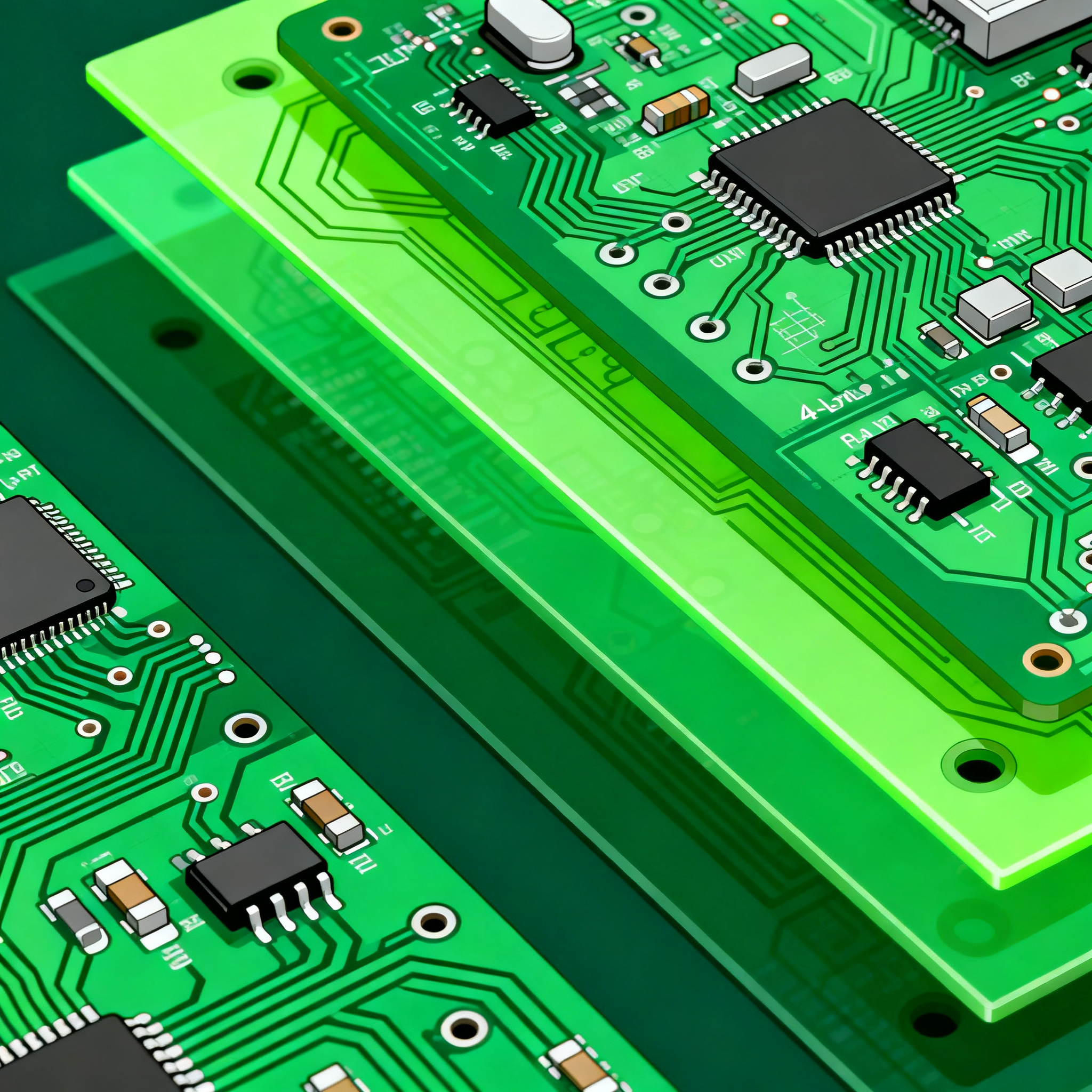
Step-by-Step Design Tutorial: Laying Out a 4-Layer Medical Industry PCB for Wearable Patient Monitors
Step-by-Step Design Tutorial: Laying Out a 4-Layer Medical PCB for Wearable Patient Monitors Why Wearable Patient Monitors Push PCB Designers Beyond Consumer Electronics Wearable medical monitors live...
Step-by-Step Design Tutorial: Laying Out a 4-Layer Medical PCB for Wearable Patient Monitors
Why Wearable Patient Monitors Push PCB Designers Beyond Consumer Electronics
Wearable medical monitors live in a world that consumer fitness bands never see. A patient-worn ECG patch or multi-parameter monitor must survive constant skin contact, perspiration, motion artifacts, and the scrutiny of clinical validation—all while remaining thin and unobtrusive enough for 24-hour wear. The PCB inside isn’t just a circuit carrier; it’s a safety barrier, a noise shield, and a mechanical flex element rolled into one.
The journey from concept to a clinically trialed device, as outlined in Cad Crowd’s medical product design guide, demands that the PCB layout support both pilot prototypes and final production without redesign. A pilot prototype of a medical device is intended for clinical trials, meaning the board you lay out today must already meet essential performance and isolation requirements. You can’t treat the first spin as a “rough draft” and fix safety gaps later—regulatory bodies expect the design to be mature from the first human-use build.
Medical PCBs also carry a unique burden: the applied part. Electrodes touching the patient create a conductive path that must be isolated from secondary circuits, even when the device runs on a single Li-ion cell. Amendment 1 to IEC 60601-1, as noted by Kolabtree’s medical device design guide, introduced requirements for human factors, essential performance, and usability that ripple down to the board level. Your layout must account for creepage distances, insulation barriers, and test points that let you verify isolation during production—not as an afterthought.
Meanwhile, the analog front-end (AFE) that picks up microvolt-level biopotential signals sits millimeters away from a Bluetooth Low Energy (BLE) radio and a switching regulator. Without a disciplined stackup and partitioning strategy, motion artifacts and digital noise will swamp the ECG waveform, making the device clinically useless. PCBRunner’s medical PCB guide stresses that a medical PCB starts with a noise-conscious schematic and a layout that isolates sensitive analog front-ends from digital noise. This tutorial walks you through that exact process for a 4-layer board, from stackup selection to design verification.
Mapping Signal Layers and Ground Planes: A 4-Layer Stackup That Suppresses Motion Artifacts
When you’re routing a wearable patient monitor, the 4-layer stackup isn’t just about squeezing traces into fewer layers. It’s about creating a low-impedance return path for every signal, shielding high-impedance biopotential inputs from electric fields, and maintaining controlled impedance for digital buses. The stackup below has been proven on dozens of ECG and multi-parameter patches and is a solid starting point for any battery-powered medical wearable.
| Layer | Material / Copper Weight | Assignment | Key Parameters |
|---|---|---|---|
| Top (L1) | 0.5 oz Cu + ENIG finish | High-impedance analog signals (ECG, respiration), guard traces, AFE components | 50 Ω single-ended (if needed); 0.15 mm minimum trace/space |
| Core (prepreg) | 0.2 mm FR-4 (or polyimide for flex) | — | Dk ~4.2–4.5 at 2.4 GHz |
| Ground (L2) | 1 oz Cu | Solid ground plane, unbroken under analog and digital sections | Return path for all signals; plane splits only if galvanic isolation is required |
| Core (laminate) | 0.5–0.8 mm FR-4 | — | Thickness sets board rigidity and impedance |
| Power / Digital (L3) | 1 oz Cu | Power polygons (3.3 V, 1.8 V), digital routing (SPI, I²C, UART), BLE module traces | 20 mil minimum trace width for power; keep digital signals away from board edge |
| Prepreg | 0.2 mm | — | — |
| Bottom (L4) | 0.5 oz Cu | Low-speed control signals, test points, battery connection, optional shield plane | Flood fill with ground pour tied to L2 with stitching vias every 5 mm |
Why this stackup works. Placing the solid ground plane on L2 directly beneath the high-impedance analog traces on L1 minimizes loop area and provides a predictable return path. The thin 0.2 mm dielectric between L1 and L2 keeps the ground plane close, which reduces crosstalk and improves shielding against external noise—critical when the device is worn on the body and subjected to 50/60 Hz power-line fields. The power and digital layer (L3) is buried between two ground references (L2 and the L4 ground pour), containing fast edge rates and preventing them from coupling onto the sensitive top layer.
Guard rings and partitioning. For ECG or EEG channels, route a guard trace around each high-impedance input pin, driven by a buffered version of the signal. This guard ring should be placed on L1 and connected to the AFE’s guard output. Never run digital traces parallel to analog inputs on the same layer; if they must cross, do so on adjacent layers with the ground plane in between. Partition the board physically: place the AFE and its passive components on one side of the PCB, the BLE module and digital logic on the other, with the power management IC in the middle. This physical separation reinforces the stackup’s electrical isolation.
Motion artifact suppression. Motion artifacts often originate from triboelectric noise in cables and connectors, but the PCB itself can contribute if the board flexes. Use a rigid-flex construction (discussed in the next section) or at least specify a low-modulus solder mask and avoid placing ceramic capacitors near high-stress areas. The solid ground plane on L2 also acts as a shield against electric fields generated by clothing rubbing against the enclosure.
When to Choose Polyimide Over FR-4 for a Sweat-Proof Wearable Monitor
Wearable patient monitors spend hours against sweaty skin, get bent as the patient moves, and must survive repeated cleaning with disinfectants. The substrate you choose determines whether the board delaminates after a week or lasts through a 30-day Holter study. Three material families dominate medical wearables: standard FR-4, high-Tg FR-4, and polyimide. Each has a place, and the decision hinges on flexibility requirements, moisture resistance, and cost.
| Comparison Metric | Standard FR-4 (e.g., Shengyi S1141) | High-Tg FR-4 (e.g., Isola 370HR) | Polyimide (e.g., DuPont Pyralux AP) | Selection Criteria & Failure Boundary |
|---|---|---|---|---|
| Glass Transition Temperature (Tg) | 130–140 °C | 170–180 °C | 250 °C+ (polyimide core) | Choose high-Tg if reflow peaks exceed 230 °C; polyimide for repeated thermal cycling |
| Moisture Absorption (24 h) | 0.15–0.25% | 0.10–0.15% | 0.4–0.8% (adhesive-based); 0.2% (adhesiveless) | FR-4 outperforms polyimide in moisture uptake; but polyimide survives liquid ingress without CAF growth |
| Flexural Modulus / Flexibility | Rigid only (≥3.5 GPa) | Rigid only (≥3.5 GPa) | Flexible; can be bent to <1 mm radius repeatedly | Use polyimide for any dynamic or static flex zone; FR-4 stiffeners only in component areas |
| Dielectric Constant (Dk) at 2.4 GHz | 4.2–4.5 | 3.8–4.0 | 3.2–3.5 | Lower Dk in polyimide helps maintain antenna efficiency in flex regions |
| Relative Cost (per sq. in., 4-layer) | 1x (baseline) | 1.3–1.5x | 3–5x | Standard FR-4 for rigid patches; polyimide only for flex-to-install or dynamic bending |
| Typical Application | Rigid chest strap, bedside monitor module | Leadless ECG patch with BLE, where rework cycles are high | Flexible patch that conforms to arm or chest, rigid-flex designs | Match the mechanical design: if the board must bend during wear, polyimide is mandatory |
For most wearable monitors, a pure rigid board is uncomfortable and prone to electrode detachment. The sweet spot is a rigid-flex construction: FR-4 stiffeners in component areas (where the AFE, BLE module, and battery connector sit) and polyimide flex layers in the bending zone that connects electrodes or wraps around a limb. This approach, detailed in many medical device design guides including Elexes’s FDA and ISO 13485 guide, lets you keep component costs low while meeting the mechanical demands of skin-contact wearables.
Sweat-proofing considerations. Polyimide absorbs more moisture than FR-4, but it does not suffer from conductive anodic filament (CAF) growth the way FR-4 does when contaminated with ionic fluids. If you use FR-4 in a sweat-exposed area, specify a conformal coating (parylene or acrylic) and avoid routing high-impedance nodes near the board edge. For polyimide flex layers, choose an adhesiveless construction to minimize moisture wicking along the adhesive layer. Always discuss the expected use environment with your PCB fabricator—NovaPCBA’s engineering team regularly advises on material selection for medical PCB assembly and can provide test coupons for moisture ingress validation.
Designing Creepage and Isolation into Your 4-Layer Board to Meet IEC 60601-1
Even a battery-powered wearable patient monitor falls under IEC 60601-1 because the electrodes form an applied part. The standard’s Amendment 1, as highlighted by Kolabtree’s step-by-step guide, requires that you evaluate essential performance and usability, not just basic insulation. That means your layout must guarantee that a single fault—a solder bridge, a cracked component, or insulation breakdown—does not put the patient at risk.
For a 4-layer board, creepage and clearance distances are set by the working voltage, pollution degree, and material group. A typical wearable monitor with a 3.7 V Li-ion cell and an isolated ECG front-end might have the following spacing requirements, assuming Pollution Degree 2 and Material Group IIIa (FR-4):
| Insulation Barrier | Working Voltage | Required Creepage (mm) | Required Clearance (mm) | Layout Implementation |
|---|---|---|---|---|
| Patient-connected circuit to secondary (non-isolated) | 3.7 V DC (but considered mains-referenced if charger connected) | 4.0 mm (basic insulation) | 2.0 mm | Route isolated side on L1 with keep-out zone; no copper on L2 under barrier |
| Between isolated ground and chassis/enclosure | 3.7 V DC | 2.5 mm | 1.5 mm | Use a slot in the PCB or a wide routing channel on all layers |
| Across an optocoupler or digital isolator | 3.7 V to 3.3 V (internal) | 4.0 mm (reinforced if no protective earth) | 2.0 mm | Place isolator straddling the isolation boundary; no traces crossing the gap |
| Battery terminals to patient-connected circuit | 4.2 V max | 2.0 mm | 1.2 mm | Keep battery connector on secondary side, away from electrode vias |
Tip: Even if your device is purely battery-operated, consider the worst-case scenario where the patient touches a mains-powered device (like a phone charger) while wearing the monitor. This is why many teams design to 4 mm creepage between the applied part and any accessible secondary circuit, as a conservative risk control.
Beyond spacing, the layout must support production testing of isolation. Include test points on the isolated side that let a hipot tester verify 500 V DC insulation resistance between patient connections and the BLE antenna or USB pins. Document these test points in the PCB fabrication notes and link them to the design FMEA. Elexes’s design controls guide explains how FDA design history file requirements demand traceability from risk controls (like isolation barriers) to layout features. Use version-controlled outputs for schematics, stackup drawings, and Gerber files, and maintain a traceability matrix that maps each isolation barrier to the DFMEA line item that justifies it.
Questions Senior Engineers Ask Before Signing Off a Medical Wearable PCB Design
Below are the questions that surface during design reviews, regulatory audits, and pre-clinical trial checks—and the answers that demonstrate your layout is ready for production and patient use.
Q: What minimum creepage distance should I maintain on a 4-layer board for a wearable patient monitor powered by a single Li-ion cell?
Even with a 3.7 V supply, IEC 60601-1 considers the applied part (electrodes) as patient-connected. Maintain at least 4 mm creepage between patient-connected circuits and secondary circuits unless you perform a documented risk analysis to justify reduced spacing. This 4 mm value comes from the standard’s tables for 50 V DC working voltage with Pollution Degree 2, and it provides margin for the transient overvoltages that can occur if the patient contacts another electrical device. Always verify the final spacing with your test lab, as they may require additional margin for manufacturing tolerances.
Q: Can I use standard FR-4 for a flex-to-install rigid-flex design, or must I switch to polyimide for the flex layers?
Standard FR-4 is rigid and cannot be used in any flex region, even for a one-time “flex-to-install” bend. For any dynamic or static flex area, you must use polyimide flex layers. A common and cost-effective approach is a rigid-flex stackup with FR-4 stiffeners only in component areas and polyimide in the bending zone. This avoids the expense of a fully flexible polyimide board while still providing the necessary mechanical compliance. Work with your fabricator to define the bend radius and layer count in the flex section; NovaPCBA’s rigid-flex capabilities support medical designs with up to 8 layers in the rigid section and 2–4 flex layers.
Q: How do I handle mixed-signal grounding when the ECG front-end shares a return path with a BLE module?
Use a single solid ground plane on layer 2 and partition components, not the plane. Splitting the ground plane creates a dipole that radiates and picks up noise. Instead, place the AFE on one side of the board and the BLE module on the other, with the power management IC in between. Route sensitive analog signals away from the BLE antenna keep-out area (typically a 5–10 mm clearance on all layers) and surround the AFE with a guard ring driven by the AFE’s guard output. If galvanic isolation is required between the patient-connected circuit and the BLE radio, use a separate ground for the isolated side, tied to the secondary ground through a single safety-rated Y-capacitor (e.g., 100 pF, 250 V AC) at the isolation boundary. This maintains high-frequency continuity while blocking DC fault currents.
Q: What design verification tests does the PCB need to pass before clinical trials?
At a minimum, your board must pass: signal integrity eye diagrams for digital buses (SPI, I²C) to ensure clean data transfer; noise floor measurement on analog inputs with the device worn on a human subject (target <10 µV peak-to-peak in 0.5–40 Hz band for ECG); ESD immunity to IEC 61000-4-2 at ±8 kV contact discharge applied to accessible parts; and insulation resistance testing between patient-connected circuits and the enclosure (typically >10 MΩ at 500 V DC). Many teams also perform accelerated life testing for flex interconnects, bending the rigid-flex zone through 100,000 cycles while monitoring continuity. Document all results in the design history file.
Q: How do I document the PCB layout to satisfy FDA design history file requirements?
Maintain version-controlled outputs of the schematic, layout, stackup drawing, and fabrication notes. Each revision must be linked to design review minutes and include a traceability matrix showing how layout features fulfill risk controls identified in the DFMEA. For example, if the DFMEA requires a 4 mm creepage barrier between the AFE and BLE, the layout document should explicitly call out that spacing with a dimensioned drawing. Tools like Altium 365 or Git-based hardware revision control (using Git for KiCad or Eagle files) help automate version tracking and provide an audit trail. The Elexes medical device design guide offers a detailed breakdown of FDA design controls and ISO 13485 documentation expectations that directly influence how you structure your PCB release package.
References & Further Reading
- Designing New Medical Products & Devices: A Step-by-Step Guide for Your Company | Cad Crowd
- Medical Device Design: The Essential, Step-by-Step Guide | Kolabtree
- Step-by-Step Guide to Medical PCB Design for Medical Devices | PCBRunner
- Medical Device Design & Development Guide | FDA & ISO MDR | Elexes
- IPC-2221: Generic Standard on Printed Board Design
- IEC 60601-1: Medical electrical equipment – Part 1: General requirements for basic safety and essential performance
- Medical PCB Assembly Services – NovaPCBA
- Rigid-Flex PCB Manufacturing & Assembly – NovaPCBA
This tutorial reflects real-world practices used by NovaPCBA’s engineering team when supporting medical device startups and established OEMs. From stackup consultation to full turnkey assembly of 4-layer rigid-flex patient monitors, our medical PCB assembly line is set up to handle the tight tolerances, material certifications, and traceability that IEC 60601-1 and FDA design controls demand. Reach out to discuss your next wearable monitor build.