Introduction
In the fast-paced world of electronics manufacturing, Surface Mount Technology (SMT) assembly plays a crucial role in producing efficient and high-performance electronic devices. As the demand for smaller and more powerful devices grows, the need for precise and efficient SMT processes becomes increasingly important. This article delves into the SMT assembly process flow, focusing on troubleshooting common pitfalls to enhance production efficiency. By understanding component specifications, datasheets, selection criteria, and application circuits, manufacturers can streamline their processes and improve product quality.
Technical Overview
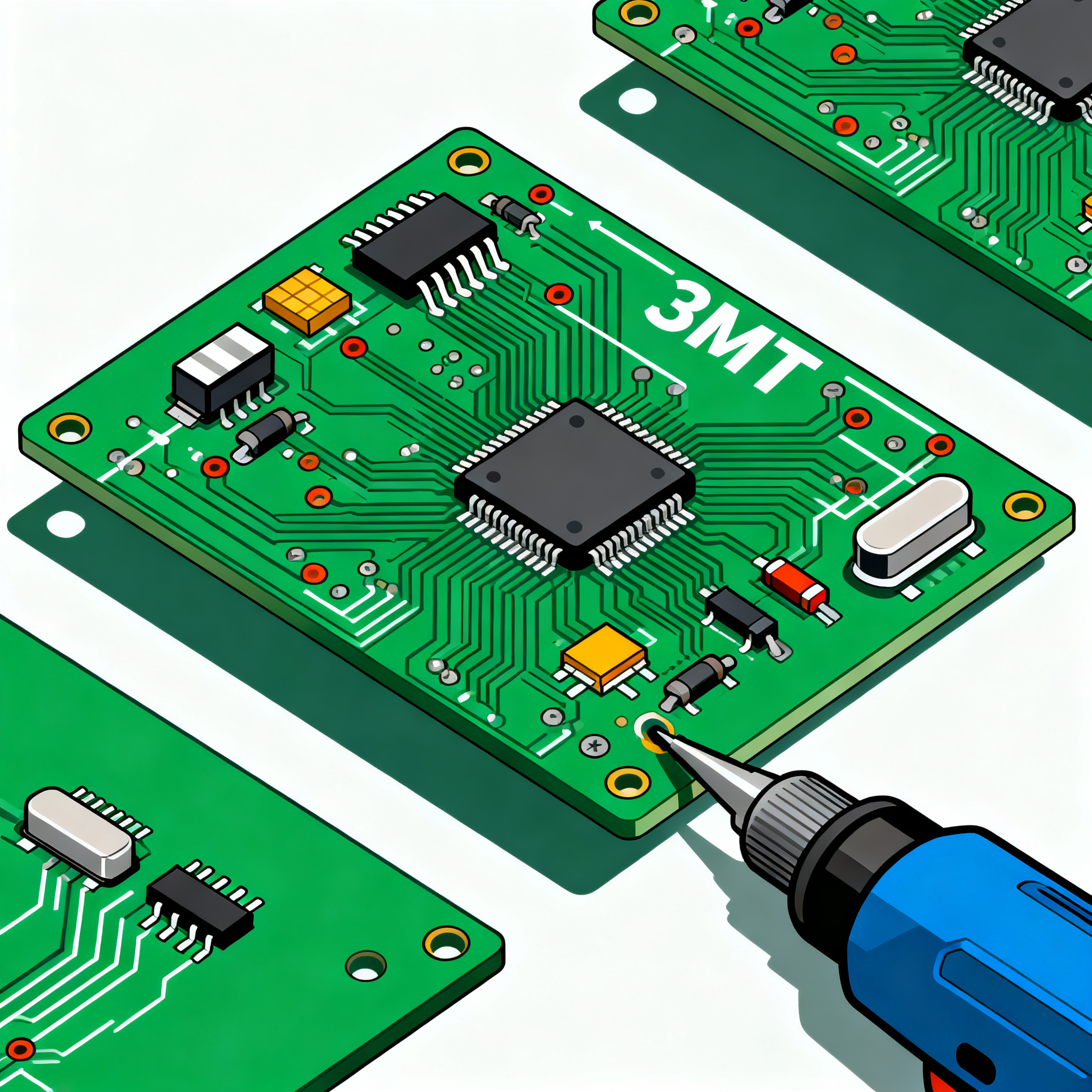
Surface Mount Technology (SMT) is a method for producing electronic circuits in which components are mounted directly onto the surface of printed circuit boards (PCBs). This technique is widely used due to its ability to increase circuit density and reduce manufacturing costs. SMT assembly involves several key steps: solder paste application, component placement, reflow soldering, inspection, and testing.
The core architecture of SMT assembly revolves around the use of specialized equipment such as stencil printers, pick-and-place machines, and reflow ovens. These machines work in harmony to ensure that components are accurately placed and soldered onto the PCB. The principles of SMT assembly emphasize precision, speed, and reliability, as even minor errors can lead to significant defects and production inefficiencies.
Understanding the specifications and characteristics of components, such as integrated circuits (ICs), is vital in the SMT process. This includes examining datasheets for information on CPU speed, memory, peripherals, power requirements, and packaging. Proper component selection and application circuit design can prevent common pitfalls and enhance overall production efficiency.
Detailed Specifications
When selecting components for SMT assembly, it's essential to consider several specifications that impact performance and compatibility. These include CPU speed, memory capacity, peripheral interfaces, power consumption, and packaging type. Understanding these specifications helps in making informed decisions during the design and manufacturing phases.
| Specification | Value | Description |
| CPU Speed | 1.5 GHz | Processor speed for high-performance applications |
| Memory | 2 GB | RAM capacity for efficient data processing |
| Peripherals | USB, I2C, SPI | Interfaces for connecting external devices |
| Power Consumption | 5W | Energy usage under typical load |
| Package Type | LQFP | Low-profile quad flat package for compact design |
| Temperature Range | -40°C to 85°C | Operating temperature for reliability |
| Voltage Range | 1.8V to 3.3V | Operating voltage for stability |
| Dimensions | 10mm x 10mm | Package size for space-constrained applications |
| Pin Count | 64 | Number of pins for connectivity |
| Data Bus Width | 32-bit | Data handling capability |
| Frequency | 100 MHz | Clock frequency for synchronization |
Key Takeaways from the Specifications
Understanding the core specifications of an integrated circuit is crucial for optimizing the SMT assembly process. The CPU speed and memory capacity determine the processing power and efficiency of the device, making them critical factors in high-performance applications. Peripheral interfaces like USB, I2C, and SPI provide flexibility for connecting various external devices, enhancing the functionality of the final product. Power consumption and operating voltage are key considerations for energy efficiency and stability, especially in battery-powered applications. The package type, dimensions, and pin count play significant roles in the physical design and assembly of the PCB, impacting the overall form factor and connectivity of the device.
| Parameter | Min | Max |
| Operating Voltage | 1.8V | 3.3V |
| Supply Current | 10 mA | 500 mA |
| Input Voltage High | 1.5V | — |
| Input Voltage Low | — | 0.4V |
| Output Current | -20 mA | 20 mA |
| Clock Frequency | 10 MHz | 100 MHz |
| Propagation Delay | — | 10 ns |
| Output Voltage High | 2.9V | 3.3V |
| Output Voltage Low | 0V | 0.4V |
| ESD Protection | 2 kV | — |
| Leakage Current | — | 1 µA |
Practical Implications
The electrical characteristics of an IC are pivotal in ensuring reliable performance and compatibility with other components in the circuit. Operating voltage and supply current define the power requirements, influencing the choice of power supply and battery life in portable devices. Input and output voltage levels are critical for interfacing with other digital components, ensuring proper logic level compatibility. Parameters like propagation delay and clock frequency impact the timing and speed of data processing, which are crucial for synchronous applications. ESD protection and leakage current specifications ensure the robustness and efficiency of the IC in various environmental conditions.
| Application | Configuration | Benefits |
| Consumer Electronics | High-speed CPU, Low power | Enhanced user experience, energy-efficient |
| Industrial Automation | Robust I/O, High durability | Reliable operation in harsh environments |
| Automotive Systems | Wide temperature range, Low EMI | Safety and reliability under extreme conditions |
| Medical Devices | Low power, High precision | Extended battery life, accurate measurements |
| Networking Equipment | High throughput, Low latency | Fast data processing, improved connectivity |
| Wearable Technology | Compact size, Low power | Portability, extended usage time |
| Telecommunications | High frequency, Wide bandwidth | Enhanced signal processing capabilities |
Application Guidelines
Selecting the right configuration for specific applications is crucial in optimizing performance and efficiency. In consumer electronics, a high-speed CPU paired with low power consumption enhances user experience and extends battery life. Industrial automation requires robust I/O and high durability to withstand harsh environments, ensuring reliable operation. Automotive systems benefit from a wide temperature range and low EMI, crucial for safety and reliability. In medical devices, low power and high precision are essential for extended battery life and accurate measurements. Understanding these application-specific requirements helps in making informed decisions during component selection and circuit design.
Design Considerations
Designing an efficient SMT assembly process involves several critical considerations. Firstly, component selection should align with the application requirements, considering factors such as performance, power consumption, and environmental conditions. It's essential to consult datasheets and adhere to industry standards like IPC-A-610 and IPC-2221 to ensure compatibility and quality.
PCB layout plays a significant role in the overall performance and reliability of the assembly. Proper placement and routing of components minimize signal interference and thermal issues. Designers should also consider the manufacturability of the PCB, ensuring that the design aligns with the capabilities of the assembly equipment and processes.
Thermal management is another vital aspect, as excessive heat can lead to component failure and reduced lifespan. Implementing effective heat dissipation techniques, such as heat sinks and thermal vias, helps maintain optimal operating temperatures.
Quality control and inspection are crucial in identifying and rectifying defects early in the process. Automated optical inspection (AOI) and X-ray inspection are commonly used to detect soldering defects and misaligned components.
Finally, collaboration with PCB assembly partners, such as those provided by PCBWay and Nova PCBA, ensures access to advanced manufacturing capabilities and expertise, further enhancing the quality and efficiency of the SMT assembly process.
Step-by-Step Implementation
Implementing an efficient SMT assembly process involves several detailed steps:
- Design and Layout: Begin with a comprehensive design and layout that considers component specifications, PCB dimensions, and manufacturability. Use CAD tools to create a detailed schematic and layout.
- Solder Paste Application: Apply solder paste to the PCB using a stencil printer. Ensure even distribution to prevent bridging and insufficient solder joints.
- Component Placement: Use a pick-and-place machine to accurately position components onto the PCB. Verify alignment and orientation to prevent placement errors.
- Reflow Soldering: Heat the assembly in a reflow oven to melt the solder paste and establish secure connections. Monitor temperature profiles to avoid overheating and thermal stress.
- Inspection: Conduct automated optical inspection (AOI) to identify defects such as misaligned components, insufficient solder, and bridging. Use X-ray inspection for hidden joints.
- Testing: Perform functional testing to verify the electrical performance and functionality of the assembled PCB. Identify and rectify any issues before final assembly.
- Rework and Repair: Address any defects identified during inspection and testing. Use soldering tools and techniques to rework and repair faulty components and connections.
- Final Assembly and Packaging: Once all defects are resolved, proceed with the final assembly and packaging. Ensure that the product meets quality standards and specifications.
Common Issues & Solutions
Despite careful planning and execution, common issues can arise during the SMT assembly process. Here are some real problems and their solutions:
- Bridging: Excess solder can lead to bridging between adjacent pads. Solution: Adjust stencil thickness and solder paste volume to prevent excess application.
- Insufficient Solder Joints: Inadequate solder can result in weak joints. Solution: Ensure proper stencil alignment and adjust the reflow temperature profile.
- Misaligned Components: Components may shift during placement. Solution: Calibrate the pick-and-place machine and use fiducial marks for accurate alignment.
- Component Tombstoning: Uneven heating can cause components to stand on end. Solution: Optimize reflow profiles and ensure even heat distribution.
- Delamination: Excessive moisture can cause PCB delamination during reflow. Solution: Store PCBs in a controlled environment and pre-bake to remove moisture.
- Open Circuits: Poor soldering can lead to open circuits. Solution: Inspect solder joints using AOI and rework any defective connections.
Applications & Use Cases
SMT assembly is widely used across various industries due to its versatility and efficiency. In consumer electronics, it enables the production of compact and powerful devices like smartphones and tablets. Industrial automation benefits from SMT's ability to produce durable and reliable control systems. Automotive applications rely on SMT for advanced driver-assistance systems (ADAS) and infotainment systems. In the medical field, SMT is used to create precise and energy-efficient devices such as portable diagnostic tools and monitoring equipment. The telecommunications industry leverages SMT for high-speed networking equipment, enhancing data processing and connectivity.
Selection & Sourcing Guide
Selecting and sourcing the right components for SMT assembly is crucial for ensuring quality and performance. Utilize resources like
IC Online to access a wide range of components and datasheets. Consider factors such as lead time, cost, and supplier reputation when sourcing components. Collaborate with reliable suppliers to ensure timely delivery and consistent quality. Additionally, leverage tools and platforms that provide real-time inventory updates and component availability to streamline the sourcing process.
FAQ
- What is SMT assembly? SMT assembly is a method of producing electronic circuits by mounting components directly onto the surface of PCBs.
- Why is component specification important in SMT? Component specifications determine performance, compatibility, and reliability, impacting the overall quality of the assembly.
- How can I prevent common SMT assembly issues? Proper design, component selection, and process optimization help prevent issues like bridging, misalignment, and insufficient solder joints.
- What role does reflow soldering play in SMT? Reflow soldering is essential for establishing secure connections between components and the PCB by melting the solder paste.
- How do I choose the right components for my application? Consider specifications like CPU speed, power consumption, and environmental conditions to select components that meet application requirements.
- What is the significance of IPC standards in SMT? IPC standards provide guidelines for PCB design, assembly, and quality inspection, ensuring consistency and reliability in manufacturing.
- How do I handle thermal management in SMT designs? Implement heat dissipation techniques like heat sinks and thermal vias to maintain optimal operating temperatures.
- What are the benefits of using automated inspection in SMT? Automated inspection helps identify defects early in the process, reducing rework and improving product quality.
- How can I ensure a reliable supply of components? Collaborate with reputable suppliers and use platforms that provide real-time inventory updates for efficient sourcing.
- What are some common applications of SMT assembly? SMT assembly is used in consumer electronics, industrial automation, automotive systems, medical devices, and telecommunications.
Conclusion
In conclusion, understanding the SMT assembly process flow, component specifications, and application guidelines is essential for improving production efficiency and product quality. By addressing common pitfalls and leveraging advanced manufacturing techniques, manufacturers can optimize their processes and deliver high-performance electronic devices. With the right design considerations, implementation steps, and troubleshooting strategies, SMT assembly can meet the demands of various industries and applications, driving innovation and technological advancement.