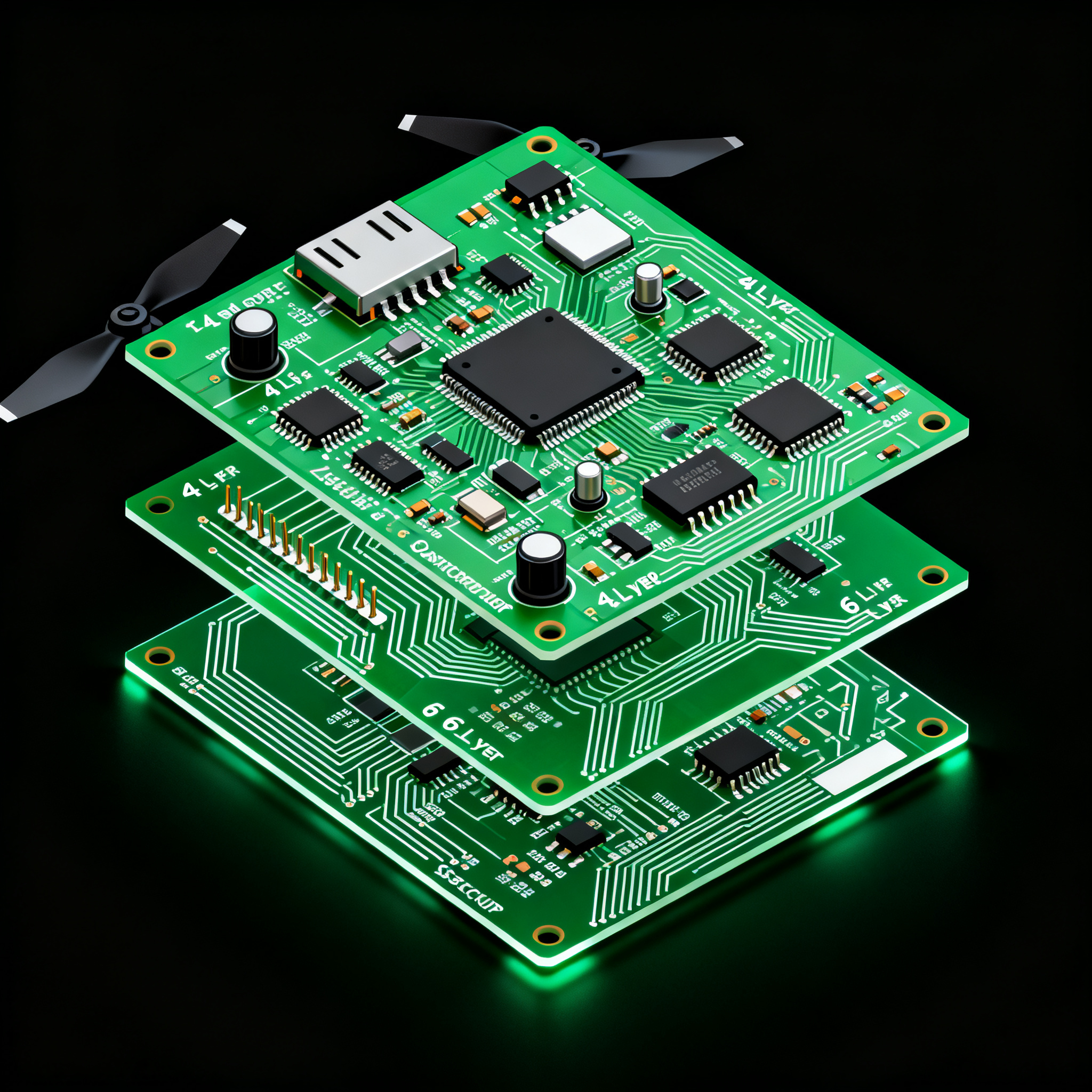
Professional Drone PCB Assembly: 4-Layer vs. 6-Layer Stackup Selection Guide for High-Speed Flight Controllers
When a 4‑Layer Flight Controller Isn’t Enough: Signal Integrity Risks That Ground Drones High‑speed drone flight controllers operate in a brutal physical environment, but the first cracks often appear...
When a 4‑Layer Flight Controller Isn’t Enough: Signal Integrity Risks That Ground Drones
High‑speed drone flight controllers operate in a brutal physical environment, but the first cracks often appear in the PCB stackup. A 4‑layer board that works flawlessly on a standalone flight controller can degrade into signal integrity failures, power delivery noise, and thermal hotspots the moment you integrate electronic speed controllers (ESCs) or dense sensor suites. Industry field data is unambiguous: five board‑level problems—poor impedance control, insufficient thermal relief, vibration‑induced solder joint fatigue, via cracking, and delamination—repeatedly ground commercial and industrial UAVs (AdvancedPCB). For standalone flight controllers, a 4‑layer stackup still works well, but once you integrate ESCs or high‑bandwidth peripherals, 6 layers become the path to reliability (PCBSync). This section maps the real‑world failure modes that make stackup selection a first‑order design decision, not a cost trade‑off.
Engineers who have redesigned failed 4‑layer boards know the pattern: a single buried via carrying ESC return current cracks after thermal cycling, the ground plane is cut by high‑current traces, and differential pairs lose their reference. The result is erratic IMU data, intermittent motor sync, and in‑flight resets. AdvancedPCB’s analysis of UAV field returns highlights that solder joint fatigue under vibration and delamination caused by localized overheating are the two most expensive failures to diagnose post‑deployment. The common root cause is a stackup that cannot carry the mechanical and thermal loads imposed by integrated power stages.
PCBSync explicitly recommends moving to 6 layers when ESCs are integrated onto the flight controller board. The additional layers provide uninterrupted reference planes, dedicated routing for high‑current power stages, and the thermal mass needed to spread heat away from sensitive MEMS sensors. Without this upgrade, even exotic materials and thick copper (2 oz) cannot compensate for a lack of plane continuity. The decision to step up from 4 to 6 layers is therefore driven by physics, not feature creep.
Inside a High‑Speed Drone PCB Stackup: Impedance, Planes, and Thermal Management
A well‑designed drone stackup is about more than layer count—it’s about stitching every signal to a solid reference plane. The classic 4‑layer build (SIG‑GND‑PWR‑SIG) places all signals adjacent to a ground reference, which is why PCBSync calls it the minimum for flight controllers (PCBSync Design Guide). In this arrangement, the top and bottom signal layers are tightly coupled to the inner ground and power planes, providing a continuous return path for high‑speed digital lines. For a 0.2 mm dielectric core, a 50 Ω single‑ended trace width of roughly 0.30 mm is achievable with 1 oz copper on standard FR‑4, and 100 Ω differential pairs can be routed with appropriate spacing.
A 6‑layer stackup adds inner routing layers and split power/ground planes, giving ESCs the copper mass and thermal spread they need while keeping high‑speed digital lanes (USB 3.0, MIPI CSI‑2) within tight impedance windows. The typical sequence—SIG‑GND‑SIG‑PWR‑GND‑SIG—reserves two inner signal layers for dense routing around BGAs and high‑current ESC drivers, while solid ground planes on layers 2 and 5 sandwich the power plane and shield the outer layers. This arrangement also reduces loop inductance, which is critical for switching regulators that power flight controllers and sensor suites.
Controlled impedance is non‑negotiable for professional drone boards. With today’s process control, ±5–8 % tolerance is achievable on 6‑layer builds using precision prepregs and test coupon verification, as detailed in AllPCB’s stackup planning guide (AllPCB). Mixed‑dielectric stackups—FR‑4 Tg 170+ with Rogers inserts for RF‑critical sections—are increasingly common when the same board carries a GPS/GNSS receiver or a video transmitter. FS PCBA’s comprehensive guide confirms that selecting the right dielectric combination is a key step in maintaining consistent εr across temperature and frequency (FS PCBA).
The table below compares typical 4‑layer and 6‑layer stackup arrangements for a 1.6 mm board thickness, illustrating the trade‑offs in impedance control, thermal management, and application fit.
| Parameter | 4‑Layer Stackup (SIG‑GND‑PWR‑SIG) | 6‑Layer Stackup (SIG‑GND‑SIG‑PWR‑GND‑SIG) | Unit/Notes |
|---|---|---|---|
| Layer sequence | L1: Signal, L2: GND, L3: PWR, L4: Signal | L1: Signal, L2: GND, L3: Signal, L4: PWR, L5: GND, L6: Signal | Typical arrangement for drone flight controllers |
| Reference plane for outer signals | Adjacent GND/PWR on L2/L3 | Adjacent GND on L2 and L5 | Lower impedance loop for 6‑layer |
| Target impedance (single‑ended) | 50 Ω | 50 Ω | Trace width depends on dielectric thickness |
| Target impedance (differential) | 100 Ω | 100 Ω | USB 3.0, MIPI CSI‑2 |
| Trace width for 50 Ω (0.2 mm dielectric) | ~0.30 mm (1 oz Cu) | ~0.18 mm (inner layers), ~0.30 mm (outer layers) | FR‑4, εr ≈ 4.2–4.5 |
| Impedance tolerance achievable | ±10 % typical | ±5–8 % with controlled process | Driven by prepreg selection and PCB fab capability |
| Power plane integrity | Single power plane, often shared with digital and analog | Split power plane on L4, solid ground on L2 and L5 | Reduced crosstalk and voltage ripple |
| Thermal management | Limited copper mass; hotspots near ESC MOSFETs | Dedicated inner planes spread heat; optional thermal vias | Critical for integrated ESCs |
| Application fit | Standalone flight controllers, moderate I/O | Integrated ESCs, high‑density BGA, RF hybrids | Reliability requirement drives selection |
In practice, the move from 4 to 6 layers is not just about adding two signal layers. It’s about creating a stable electromagnetic environment where every high‑speed trace has an uninterrupted return path, and the power delivery network can handle the transient currents of multiple motor phases without ground bounce. The extra planes also provide the mechanical stiffness needed to survive vibration profiles that routinely exceed 20 g in professional UAVs.
4‑Layer vs. 6‑Layer Drone PCBs: A Side‑by‑Side Look at Cost, Density, and Thermal Performance
A direct comparison reveals the trade‑offs that separate a $45 prototype batch from a production‑ready 6‑layer flight controller. PCBA Store’s market data shows a 4‑layer 50 × 50 mm board costs about $45 for ten pieces with ENIG finish, and bare‑PCB lead times can be as short as 3–5 days for standard orders (PCBA Store). Moving to 6 layers adds routing density—enough for BGA/QFN down to 0.4 mm pitch and 0201 SMT—but also introduces tighter impedance control and often a jump to mixed materials, as seen in Rich Full Joy’s specifications (4–10 layers, FR‑4 Tg 170+ with Rogers, ±5–8 % impedance tolerance) (Rich Full Joy).
The table below quantifies the differences across key parameters that matter to engineering buyers and PCB designers. Quality metrics from aerospace‑grade suppliers like FScircuits (20+ years experience, DO‑160 certification, 99.8 % first‑pass rate) set a benchmark for demanding programs (FScircuits).
| Comparison Metric | 4‑Layer Flight Controller | 6‑Layer Flight Controller | Selection Criteria & Failure Boundary |
|---|---|---|---|
| Typical board thickness | 1.0–1.6 mm | 1.2–1.6 mm | Thin 4‑layer boards may warp under high reflow; 6‑layer adds stiffness |
| Routing density | Moderate; 0.5 mm pitch BGA possible with care | High; 0.4 mm pitch BGA, 0201 passives, blind/buried vias | Move to 6 layers if breakout requires more than two signal layers |
| Copper weight options for ESC traces | 1–2 oz outer layers | 1–2 oz outer, 1–3 oz inner layers | Integrated ESCs demand 2 oz+ inner planes; 4‑layer struggles with heat |
| Impedance tolerance (typical) | ±10 % | ±5–8 % | High‑speed differential pairs (USB 3.0, MIPI) require ≤8 % |
| Prototype cost (10 pcs, 50×50 mm, ENIG) | ~$45 | $65–$90 | Hybrid materials add 20–40 % to the base cost |
| Lead time (standard, bare PCB + assembly) | 3–5 days | 5–10 days | 6‑layer often requires engineering review and test coupon fabrication |
| First‑pass yield (aerospace‑grade supplier) | 98 %+ | 99.8 % (FScircuits DO‑160 certified) | 6‑layer with controlled impedance needs rigorous process control |
| Thermal performance (ESC integration) | Hotspots at MOSFETs; limited heat spreading | Dedicated inner planes and thermal vias lower junction temperature | If ESC current >10 A per motor, 6 layers are strongly recommended |
| Vibration resistance | Higher risk of solder joint fatigue | Additional planes reduce mechanical stress | Drones undergoing >10 g vibration should use 6‑layer stackup |
A 4‑layer board is still the right choice for a standalone flight controller that does not carry high‑current ESC traces. When the ESC is a separate module, the 4‑layer stackup provides adequate signal integrity and keeps the bill of materials low. However, many professional drone designs today integrate the ESC and flight controller on a single PCB to reduce weight and interconnects. In that case, the 6‑layer premium actually reduces total cost by avoiding field failures, warranty returns, and the engineering time spent debugging intermittent issues. The data from AdvancedPCB’s failure analysis backs this up: most drone PCB failures they see are due to board‑level problems that a well‑designed 6‑layer stackup directly addresses.
From Design Spec to Assembly: How to Choose the Right Layer Count and Supplier for Professional Drone PCBs
The decision between 4 and 6 layers must be made early in the design cycle, because it affects the entire floorplan, component placement, and thermal strategy. The following checklist distills the comparison into a practical decision flow that engineers can apply before the first schematic is complete.
| Design Requirement | Recommended Stackup | Rationale |
|---|---|---|
| Standalone flight controller, no ESC integration, moderate digital I/O | 4‑layer | Sufficient signal integrity; lowest cost and fastest lead time |
| Integrated ESCs with >10 A per motor, high‑current power traces | 6‑layer | Dedicated inner planes manage current and heat; avoids ground bounce |
| High‑speed differential pairs (USB 3.0, MIPI CSI‑2) requiring ±8 % impedance control | 6‑layer | Tighter impedance tolerance achievable with solid reference planes |
| Dense BGA breakout (0.4 mm pitch) with multiple voltage rails | 6‑layer | Additional inner signal layers simplify routing and power distribution |
| Hybrid RF/digital board (GPS, video TX) needing mixed dielectrics | 6‑layer (Rogers hybrid) | Rogers inserts on outer layers maintain low‑loss RF performance |
| Cost‑sensitive consumer drone with separate ESC board | 4‑layer | 4‑layer keeps unit cost down; reliability risk is lower with separated power stages |
| Drone operating in high‑vibration environment (agriculture, inspection) | 6‑layer | Additional planes improve mechanical stiffness and reduce fatigue failures |
Material selection is the next critical step. For most 6‑layer drone boards, FR‑4 with a glass transition temperature of 170 °C or higher is sufficient, provided the dielectric thickness and prepreg type are chosen to meet impedance targets. When the board includes RF sections—such as a GPS patch antenna feed or a 5.8 GHz video transmitter—a Rogers hybrid stackup becomes justified. The PCBA Store Ultimate Guide notes that high‑frequency laminates can be selectively placed on outer layers, keeping the core FR‑4 for cost control while achieving the necessary RF performance (PCBA Store Ultimate Guide).
When sourcing a PCB assembly partner for a 6‑layer flight controller, look beyond the basic capability statement. The AdvancedPCB failure‑prevention playbook provides a practical checklist: verify via design rules (aspect ratio, annular ring), thermal relief patterns for high‑current pads, and solder joint geometry that can survive vibration (AdvancedPCB). Capabilities like 01005 SMT placement, AOI, X‑ray inspection, in‑circuit testing, and functional test fixtures are not optional for professional drone electronics. Suppliers with aerospace certifications, such as FScircuits (20+ years, DO‑160, 99.8 % quality rate), demonstrate the process control needed for 6‑layer HDI and mixed‑material builds (FScircuits). At NovaPCBA, we support drone PCB assembly with controlled impedance, high‑Tg materials, and rigorous testing to meet the same performance benchmarks. Ask your potential partner these questions before releasing a prototype:
- Can you provide a stackup plan with calculated impedance values and test coupon locations?
- What is your minimum trace/space capability for inner layers (e.g., 75/75 µm) and how do you verify registration?
- Do you have experience with mixed‑dielectric builds (FR‑4 + Rogers) and can you share first‑article inspection reports?
- What quality metrics do you track for 6‑layer production—first‑pass yield, defect rate, and on‑time delivery?
- Can you support functional testing of assembled flight controllers, including IMU calibration and ESC current profiling?
These questions separate prototype shops from production partners who understand the stakes of a drone that cannot afford to fall out of the sky.
Stackup Selection Questions Drone PCB Designers and Buyers Ask Before Prototyping
Q: Can a 4‑layer board handle a flight controller with integrated ESCs if I use thick copper and thermal vias?
In most cases, no. The high currents and thermal loads of ESCs push the limits of a 4‑layer stackup, even with 2 oz copper. The lack of dedicated inner routing layers often forces compromises in ground‑plane continuity and impedance control. While thermal vias can help, they cannot replace a solid inner power plane for spreading heat and managing current density. PCBSync explicitly recommends moving to 6 layers when integrating ESCs to manage power distribution and heat (PCBSync). The cost of a 6‑layer board is small compared to the risk of a motor dropout or fire in flight.
Q: How does a hybrid 6‑layer stackup with Rogers material affect prototype cost and lead time?
A Rogers‑FR‑4 hybrid 6‑layer stackup typically adds 20–40 % to the prototype cost and may extend lead time by 3–5 days compared to a pure FR‑4 6‑layer board. The exact increase depends on the number of Rogers layers and the availability of the specific laminate. Manufacturers like Rich Full Joy handle such mixed‑dielectric builds routinely, but engineering review and process adjustments are needed to maintain ±5–8 % impedance control across the different materials (Rich Full Joy). For time‑sensitive projects, confirm material lead times with your supplier at the quoting stage.
Q: What impedance tolerance is realistic for high‑speed differential pairs (USB 3.0, MIPI) on a 6‑layer drone board?
With careful dielectric selection and a tightly controlled PCB process, ±5–8 % is achievable on 6‑layer drone boards. Rich Full Joy’s production specification confirms this range, and AllPCB’s stackup planning guide details how to hit it through correct trace width/spacing and prepreg selection (AllPCB). Achieving the lower end (5 %) demands a fabricator with a proven impedance control process and test coupon data for each panel.
Q: How do I verify that my PCB manufacturer can reliably produce a 6‑layer drone board with blind vias and mixed materials?
Ask for their capability statement: minimum trace/space (e.g., 75/75 µm), layer‑to‑layer registration, and evidence of controlled impedance test coupons. Suppliers like FScircuits, with aerospace certifications and a 99.8 % quality rate, can provide first‑article inspection reports, AOI, X‑ray, and functional testing data that validate 6‑layer HDI processes (FScircuits). A reputable manufacturer will also walk you through their stackup plan and highlight any design rules that could affect yield, such as minimum annular ring and aspect ratio for blind vias.
Q: What are the biggest risks of using a 4‑layer board for a drone that undergoes vibration and thermal cycling?
AdvancedPCB’s failure analysis identifies solder joint fatigue, via cracking, and delamination as the top issues (AdvancedPCB). A 4‑layer board without a dedicated power plane or with marginal thermal relief can concentrate stress, leading to intermittent connections. The 6‑layer stackup’s additional planes reduce mechanical stress and improve thermal spreading, directly addressing these failure modes. In vibration‑intensive applications like agricultural spraying or industrial inspection, the 6‑layer upgrade is a proven reliability investment.
References & Further Reading
- AdvancedPCB – 5 PCB Failures That Ground Drones, and How to Design Against Them
- PCBSync – Drone PCB Design: Complete Guide to Components, Layout & Manufacturing
- PCBSync – Drone PCB Design: Flight Controller & ESC Board Layout
- PCBA Store – How to Choose a Drone PCB Manufacturer
- Rich Full Joy – Drone PCB Assembly: Flight Controller, ESC, VTX Manufacturing
- FScircuits – Professional Drone PCB Assembly Manufacturing Services
- AllPCB – Navigating the Complexities of Drone Flight Control PCB Manufacturing
- FS PCBA – A Comprehensive Guide for Drone PCB
- PCBA Store – Ultimate Guide to Drone PCB Optimizing Design & Manufacturing
Choosing between a 4‑layer and 6‑layer stackup for a high‑speed drone flight controller is a decision that ripples through every stage of design, assembly, and field operation. A 4‑layer board remains a viable, cost‑effective choice for standalone flight controllers that do not integrate power stages. But when ESC current demands, high‑speed differential pairs, and vibration survivability enter the picture, the 6‑layer stackup is not an upgrade—it’s the baseline for reliability. By matching the stackup to the real electrical and mechanical loads, and by partnering with a manufacturer that has proven control over impedance, mixed materials, and assembly quality, drone programs can avoid the groundings that plague under‑designed boards. At NovaPCBA, we bring that level of control to every professional drone PCB assembly project, from 4‑layer prototypes to 6‑layer HDI production runs with the testing and certifications that mission‑critical UAVs demand.