Preventing PCB Design Errors: Top 10 Pitfalls and Best Practices for Engineers
Preventing PCB Design Errors: Top 10 Pitfalls and Best Practices for Engineers Introduction In the world of electronics engineering, the design and manufacturing of printed circuit boards (PCBs) are f...
Introduction
In the world of electronics engineering, the design and manufacturing of printed circuit boards (PCBs) are fundamental tasks that require meticulous attention to detail. As the backbone of electronic devices, PCBs carry the electrical signals that allow components to communicate and function. Errors in PCB design can lead to costly rework, product failures, and delayed time-to-market. Understanding the common pitfalls and best practices in PCB design is crucial for engineers aiming to create reliable and efficient electronic systems. This article delves into key aspects of PCB design, focusing on component specifications, datasheets, selection criteria, and application circuits, to help engineers avoid common mistakes and optimize their designs.
Technical Overview
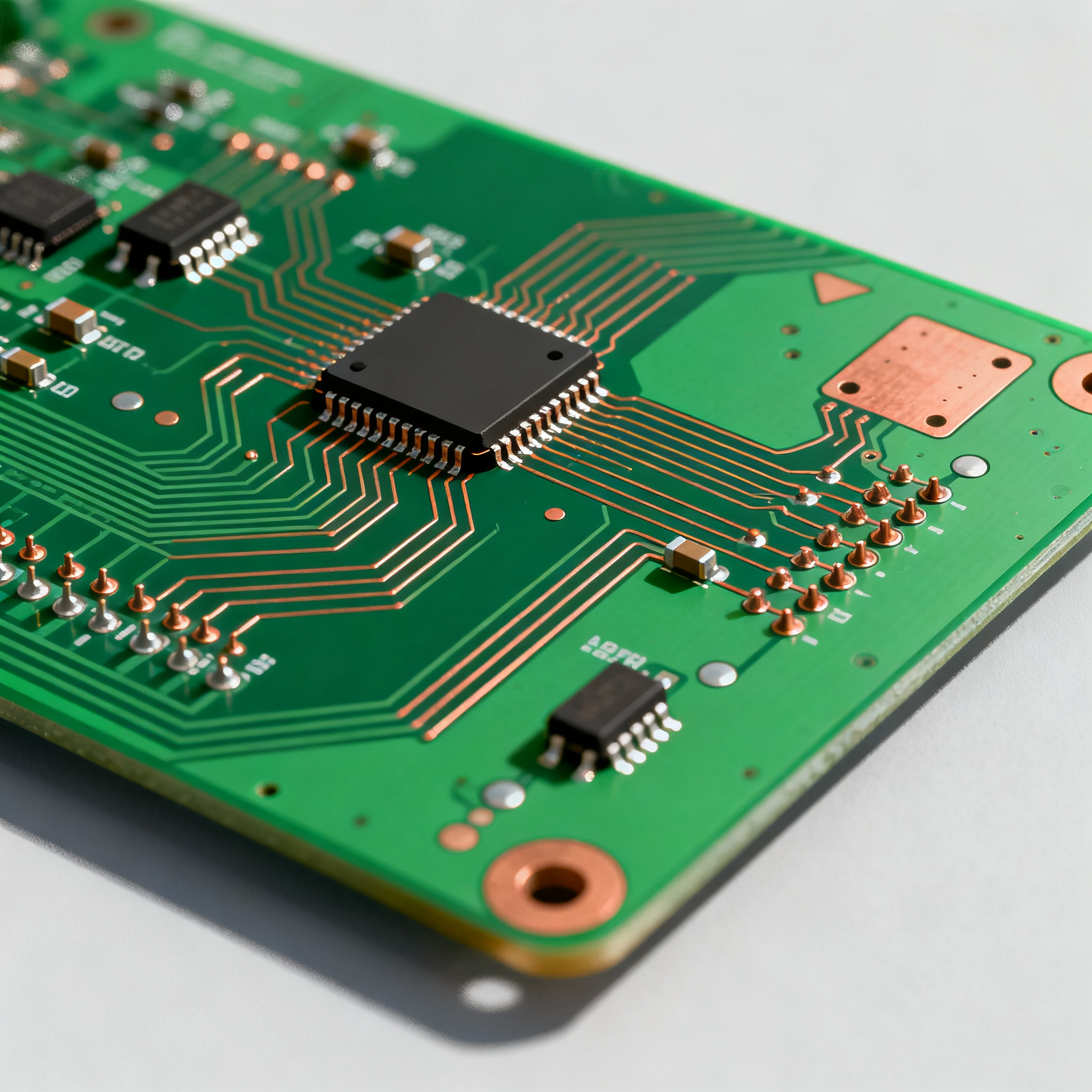
PCB design is a complex process that involves multiple stages, from schematic capture and layout design to manufacturing and assembly. The design begins with a schematic, which is a symbolic representation of the electronic circuit. This schematic is then translated into a layout, which determines the physical placement of components and routing of electrical connections on the PCB. Key considerations during this phase include signal integrity, power distribution, thermal management, and manufacturability. Engineers must also adhere to industry standards, such as those provided by the IPC, to ensure quality and reliability.
One critical aspect of PCB design is the selection of components, such as integrated circuits (ICs). This involves reviewing datasheets to understand component specifications, such as CPU speed, memory, peripherals, and power requirements. Proper component selection can significantly impact the performance and reliability of the final product. Additionally, engineers must consider the electrical characteristics of components, such as voltage, current, and timing, to ensure compatibility and optimal performance.
Application circuits are another vital consideration, as they provide guidance on how components can be used in real-world applications. Engineers must evaluate different use cases and configurations to select the most suitable components for their specific needs. By understanding these core concepts and principles, engineers can design PCBs that meet performance requirements while minimizing the risk of errors and failures.
Detailed Specifications
Component specifications are critical in PCB design, as they define the capabilities and limitations of each component. Engineers must carefully analyze these specifications to ensure that the selected components meet the requirements of their application. Key specifications include CPU speed, memory size, peripheral interfaces, power consumption, and package type. These factors influence the overall performance, functionality, and cost of the PCB. By thoroughly understanding component specifications, engineers can make informed decisions that optimize their design for both performance and manufacturability.
| Specification | Details | Importance |
|---|---|---|
| CPU Speed | 1.2 GHz | Determines processing capability |
| Memory | 512 MB RAM | Influences data handling capacity |
| Peripherals | UART, SPI, I2C | Enables communication with other devices |
| Power Consumption | 5V, 500 mA | Affects battery life and heat generation |
| Package Type | LQFP-64 | Impacts PCB layout and assembly |
| Operating Temperature | -40°C to 85°C | Defines environmental suitability |
| Flash Memory | 256 KB | Stores firmware and application code |
| GPIO Pins | 40 | Allows for expandability and customization |
| ADC Resolution | 10-bit | Determines precision of analog inputs |
| Interface | USB 2.0 | Facilitates data transfer and connectivity |
Key Takeaways from the Specifications
The core specifications table highlights essential parameters that engineers must consider when selecting components for a PCB design. CPU speed and memory are crucial for determining the processing power and data handling capacity of the device. Peripherals such as UART, SPI, and I2C enable communication with other devices, making them vital for system integration. Power consumption is another critical factor, as it impacts battery life and heat dissipation. Engineers must also consider the package type, as it influences the PCB layout and assembly process. Understanding these specifications helps engineers make informed decisions that balance performance, cost, and manufacturability.
| Characteristic | Value | Significance |
|---|---|---|
| Operating Voltage | 3.3V | Determines the power supply requirements |
| Maximum Current | 200 mA | Limits the load capacity |
| Input Voltage Range | 2.7V - 3.6V | Defines the safe operating range |
| Output Voltage Tolerance | ±5% | Affects the stability of the output |
| Propagation Delay | 10 ns | Influences timing and speed |
| Input Capacitance | 10 pF | Impacts signal integrity |
| Output Impedance | 50 Ω | Affects signal transmission quality |
| Leakage Current | 1 µA | Determines power efficiency |
| Switching Frequency | 2 MHz | Impacts power conversion efficiency |
| Thermal Resistance | 25°C/W | Determines heat dissipation capability |
Practical Implications
The electrical characteristics table provides insights into the operational parameters that affect the performance and reliability of a PCB design. Operating voltage and maximum current are critical for defining the power supply requirements and load capacity of the circuit. Input voltage range and output voltage tolerance ensure safe and stable operation. Propagation delay and input capacitance influence timing and signal integrity, which are crucial for high-speed applications. Engineers must also consider thermal resistance, as it determines the component's ability to dissipate heat and maintain optimal performance. By understanding these characteristics, engineers can design circuits that meet performance requirements while minimizing power consumption and thermal issues.
| Use Case | Configuration | Benefits |
|---|---|---|
| Consumer Electronics | Compact, low-power design | Enhanced portability and battery life |
| Industrial Automation | Robust, high-reliability components | Increased durability and performance |
| Automotive Systems | Wide temperature range components | Improved safety and reliability |
| Medical Devices | High precision, low noise circuits | Accurate and reliable measurements |
| IoT Applications | Wireless connectivity, low power | Seamless integration and energy efficiency |
| Telecommunications | High bandwidth, fast processing | Efficient data handling and transfer |
Application Guidelines
The application comparison table illustrates the diverse use cases and configurations for PCB designs. In consumer electronics, a compact and low-power design enhances portability and battery life. Industrial automation applications benefit from robust and high-reliability components that increase durability and performance. Automotive systems require components with a wide temperature range to improve safety and reliability. Medical devices demand high precision and low noise circuits for accurate measurements. IoT applications prioritize wireless connectivity and low power consumption for seamless integration and energy efficiency. Telecommunications applications focus on high bandwidth and fast processing for efficient data handling. By evaluating these use cases, engineers can select components that align with their specific application needs and optimize their PCB designs.
Design Considerations
When designing a PCB, engineers must consider a variety of factors to ensure optimal performance and reliability. Signal integrity is a critical consideration, as it affects the quality and accuracy of the electrical signals transmitted through the PCB. To maintain signal integrity, engineers must carefully route traces, minimize crosstalk, and manage impedance. Power distribution is another important factor, as it ensures that all components receive the necessary power to function properly. Engineers must design efficient power distribution networks and include adequate decoupling capacitors to minimize voltage fluctuations.
Thermal management is essential for maintaining the performance and longevity of components. Engineers must design PCBs with adequate thermal vias, heat sinks, and copper pours to dissipate heat effectively. Additionally, manufacturability is a key consideration, as it affects the ease and cost of PCB production. Engineers should adhere to industry standards, such as IPC guidelines, and work closely with manufacturing partners to ensure that their designs are feasible and cost-effective.
Component selection is another critical aspect of PCB design. Engineers must review datasheets to understand the specifications and limitations of each component. They should also consider factors such as availability, cost, and lead time when selecting components. By carefully considering these design factors, engineers can create PCBs that meet performance requirements, are easy to manufacture, and are cost-effective.
Step-by-Step Implementation
- Define the Requirements: Begin by defining the requirements of your PCB design, including the intended application, performance specifications, and environmental conditions.
- Create the Schematic: Use schematic capture software to create a symbolic representation of your circuit. Ensure that all components are correctly represented and connected.
- Select Components: Review datasheets to select components that meet your design requirements. Consider factors such as specifications, availability, cost, and lead time.
- Design the Layout: Translate the schematic into a PCB layout. Place components strategically to minimize trace lengths and optimize signal integrity.
- Perform a Design Rule Check (DRC): Use DRC tools to verify that your design adheres to industry standards and manufacturing guidelines.
- Prototype and Test: Manufacture a prototype of your PCB and conduct thorough testing to identify any issues or areas for improvement.
- Iterate and Refine: Based on testing results, make necessary adjustments to your design and repeat the prototyping and testing process.
- Finalize and Document: Once your design meets all requirements, finalize the layout and create detailed documentation for manufacturing and assembly.
Common Issues & Solutions
- Signal Integrity Problems: Use proper trace routing techniques, such as controlled impedance and differential pairs, to minimize signal integrity issues.
- Power Distribution Issues: Design efficient power distribution networks and use decoupling capacitors to minimize voltage fluctuations.
- Thermal Management Challenges: Incorporate thermal vias, heat sinks, and copper pours to dissipate heat effectively and maintain component performance.
- Manufacturing Constraints: Work closely with manufacturing partners to ensure that your design is feasible and cost-effective, and adhere to IPC standards.
- Component Availability: Consider component availability and lead time during the selection process to avoid delays in production.
- Design Rule Violations: Use design rule check (DRC) tools to verify that your design adheres to industry standards and manufacturing guidelines.
Applications & Use Cases
PCBs are used in a wide range of applications, from consumer electronics and industrial automation to automotive systems and medical devices. In consumer electronics, PCBs enable compact and portable designs, enhancing user experience and battery life. Industrial automation applications benefit from robust and high-reliability PCBs that withstand harsh environments and provide consistent performance. Automotive systems require PCBs with wide temperature ranges and high reliability to ensure safety and functionality. Medical devices demand high precision and low noise PCBs for accurate and reliable measurements. By understanding the specific requirements of each application, engineers can design PCBs that meet the unique needs of their intended use cases.
Selection & Sourcing Guide
Selecting the right components for your PCB design is crucial for ensuring optimal performance and reliability. Engineers should review datasheets to understand the specifications and limitations of each component. They should also consider factors such as availability, cost, and lead time when selecting components. For sourcing components, engineers can refer to reputable online platforms such as IC Online, which offers a wide selection of electronic components from trusted suppliers. By carefully selecting and sourcing components, engineers can create PCBs that meet performance requirements and are cost-effective.
FAQ
- What is PCB design? PCB design is the process of creating a printed circuit board, which involves schematic capture, layout design, and manufacturing.
- Why is component selection important? Component selection is crucial for ensuring that the PCB meets performance requirements and is cost-effective.
- How can I ensure signal integrity in my PCB design? Use proper trace routing techniques, such as controlled impedance and differential pairs, to maintain signal integrity.
- What are design rule checks (DRC)? DRC tools verify that your PCB design adheres to industry standards and manufacturing guidelines.
- How can I manage thermal issues in my PCB design? Incorporate thermal vias, heat sinks, and copper pours to dissipate heat effectively.
- What are the key considerations for power distribution in PCB design? Design efficient power distribution networks and use decoupling capacitors to minimize voltage fluctuations.
- How do I select the right package type for my components? Consider the impact of the package type on PCB layout, assembly, and thermal management.
- What is the importance of manufacturability in PCB design? Ensuring manufacturability reduces production costs and improves the feasibility of your design.
- How can I source components for my PCB design? Use reputable online platforms, such as IC Online, to source components from trusted suppliers.
- What are the common pitfalls in PCB design? Common pitfalls include signal integrity issues, power distribution problems, thermal management challenges, and manufacturing constraints.
Conclusion
Preventing PCB design errors requires a comprehensive understanding of component specifications, datasheets, and application circuits. By adhering to industry standards, carefully selecting components, and considering factors such as signal integrity, power distribution, and thermal management, engineers can create reliable and efficient PCB designs. This article has provided insights into common pitfalls and best practices for PCB design, helping engineers optimize their designs and avoid costly mistakes. By following these guidelines, engineers can ensure the success of their PCB projects and contribute to the development of innovative electronic systems.