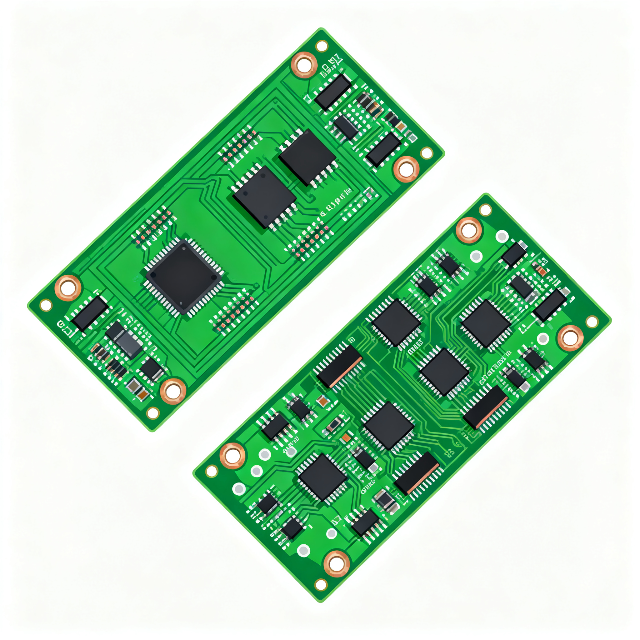
Precision Control PCB Assembly: A Side-by-Side Comparison and Selection Guide for 6-Layer Impedance-Controlled Boards
Precision Control PCB Assembly: A Side-by-Side Comparison and Selection Guide for 6-Layer Impedance-Controlled Boards Why 6-Layer Impedance Control Fails Without Precision Assembly — And What It Costs...
Precision Control PCB Assembly: A Side-by-Side Comparison and Selection Guide for 6-Layer Impedance-Controlled Boards
Why 6-Layer Impedance Control Fails Without Precision Assembly — And What It Costs You
When a 6‑layer board carries high‑speed differential pairs or a sensitive RF front‑end, the difference between a working product and a field failure often comes down to assembly precision. A stackup that simulates perfectly in your EDA tool can still deliver 20% impedance deviation if solder paste volume varies, component placement shifts, or reflow profiles drift. The consequences aren’t theoretical: we’ve seen OEMs scramble to contain field returns that traced back to a single assembly lot where a stencil cleaning lapse caused micro‑voids under BGA pads, altering the return path and pushing eye diagrams out of spec.
The six most common PCB failure mechanisms—thermal damage, plating voids, solder joint fatigue, delamination, contamination, and mechanical overstress—are all amplified when impedance control is tight and assembly margins are thin (Matric Group, 2024). In high‑volume runs, even a 2‑mil shift in component placement can change the effective dielectric spacing around a critical trace, creating a capacitive discontinuity that no amount of firmware tweaking can fix. SMT defects like insufficient solder paste, tombstoning, or head‑in‑pillow on fine‑pitch BGAs are especially punishing on 6‑layer boards because the inner reference planes are closer to the surface, so any deviation in the solder joint geometry directly alters the impedance profile (Aivon, 2024).
Beyond the immediate signal integrity hit, the lack of full traceability turns a small process excursion into a massive recall risk. When a contract manufacturer can’t link a specific panel to its paste lot, reflow profile, and placement data, you’re forced to quarantine entire shipments. A robust Device History Record (DHR) that compiles all linked data creates a complete lineage, letting you pinpoint affected batches and dramatically limit recall scope (EBest Technology). That’s why precision assembly isn’t a luxury—it’s a competitive advantage that protects your brand and your bottom line (PCBnet).
What Precision Assembly Really Means for a 6-Layer Impedance Board
Precision assembly for a 6‑layer impedance‑controlled board starts long before the pick‑and‑place machine fires up. It begins with a stackup that respects the dielectric constant (Dk) and loss tangent (Df) of the chosen prepreg and core materials, and it continues through every step of fabrication and assembly: inner‑layer registration, oxide treatment, lamination, drilling, plating, solder mask application, and finally SMT assembly. Each step can introduce variation that shifts the characteristic impedance away from your target.
On the assembly floor, three operations dominate impedance integrity: solder paste printing, component placement, and reflow. Paste volume and alignment directly affect the stand‑off height of BGAs and QFNs, which in turn changes the parasitic capacitance between the package and the reference plane. Placement accuracy—typically ±35 µm for advanced chip shooters—must hold across the entire panel, especially for 0201 passives or 0.4 mm‑pitch connectors that sit near controlled‑impedance traces. Reflow profile uniformity ensures that solder joints form consistent intermetallic layers without excessive voiding, which would create localized impedance hotspots.
Below is a representative 6‑layer stackup with the parameters that a precision assembly house must control. Tolerances are drawn from industry capability data and supplier specifications.
| Parameter | Value / Range | Unit / Notes |
|---|---|---|
| Layer count | 6 | Signal – Ground – Signal – Signal – Power – Signal (example) |
| Total board thickness | 1.60 ± 0.16 | mm; standard FR4 |
| Impedance targets | 50 Ω single‑ended, 100 Ω differential | Ω; ±10% standard, ±5% achievable with tighter control |
| Core dielectric (Layer 2–3, 4–5) | FR4, Dk 4.2–4.6 @ 1 GHz | IT‑158 or equivalent; Tg 150–170 °C |
| Prepreg dielectric (L1–L2, L3–L4, L5–L6) | FR4, Dk 4.0–4.4 @ 1 GHz | 1080 or 2116 glass style; resin content 45–55% |
| Copper weight (outer layers) | 1 oz (35 µm) finished | Starting 0.5 oz + plating |
| Copper weight (inner layers) | 0.5 oz (18 µm) | For fine‑line etching |
| Trace width / spacing (differential) | 4.5 / 7.0 mil (example for 100 Ω) | mil; depends on stackup; validated by field solver |
| Routing tolerance (standard) | ±0.05 mm | APOLLOPCB; CNC router |
| Routing tolerance (precision) | ±0.025 mm | For RF modules and edge‑launch connectors |
| Minimum via drill | 0.20 mm (mechanical), 0.10 mm (laser) | Through‑hole or blind; aspect ratio ≤ 10:1 |
| Impedance test method | TDR on coupon, per panel or batch | Rise time ≤ 35 ps; referenced to IPC‑TM‑650 |
These numbers are not aspirational—they are the baseline that a precision assembly partner must hold. JLCPCB’s published capabilities, for instance, specify minimum trace/space of 3.5/3.5 mil and controlled impedance with ±10% tolerance as standard (JLCPCB Capabilities). Achieving ±5% requires tighter material selection, more frequent TDR sampling, and a disciplined DFM process that flags impedance discontinuities before the first panel is laminated. Andwin Circuits reinforces that control board assembly efficiency hinges on integrating these fabrication tolerances with assembly process controls—solder paste inspection (SPI), automated optical inspection (AOI), and real‑time reflow profiling—so that the final board matches the simulated impedance within the allowed window (Andwin Circuits).
Side-by-Side: How Leading 6-Layer PCB Assembly Services Compare on Impedance Precision
Not all suppliers treat impedance control with the same rigor. The table below compares three manufacturers that publicly document their 6‑layer capabilities, focusing on the parameters that matter most for precision assembly of controlled‑impedance boards. The data is drawn from their published technical literature and application notes.
| Comparison Metric | Wonderful PCB (1) | JLCPCB (2), (3) | JHYPCB (4) | Selection Criteria & Failure Boundary |
|---|---|---|---|---|
| Impedance tolerance (standard) | ±10% | ±10% | ±10% | Acceptable for DDR3, USB 3.0, and general high‑speed logic when layout is clean. |
| Impedance tolerance (tight) | ±5% (with DFM review and TDR on all panels) | ±5% available on request; may require wider trace adjustments | ±5% for advanced builds, but lead time and cost increase | Mandatory for 10‑Gbps SerDes, PCIe Gen 4/5, or RF front‑ends. Verify Cpk data. |
| TDR testing | Coupon per panel; full TDR report with waveform plots | Coupon testing; batch sampling for standard orders | TDR available; typically on coupons, panel‑level by arrangement | For critical links, insist on panel‑level TDR with traceability to the serial number. |
| DFM review for impedance | Comprehensive DFM that flags impedance discontinuities, suggests stackup tweaks | Automated DFM check; manual engineering review for controlled‑impedance orders | Engineering review included; focuses on manufacturability and cost optimization | A supplier that doesn’t offer a stackup‑specific DFM review is a red flag for ±5% builds. |
| Layer registration tolerance | ±3 mil (76 µm) | ±4 mil (100 µm) standard; ±3 mil for advanced | ±3 mil | Tighter registration preserves trace‑to‑reference spacing; critical for differential pairs. |
| Via capabilities (blind/buried) | Laser blind vias, buried vias, sequential lamination | Blind/buried vias supported; stackup complexity may extend lead time | Blind/buried vias available; 6‑layer with blind vias adds 3–5 days | Use blind vias to eliminate stubs above 1 GHz; check aspect ratio limits. |
| Typical lead time (6‑layer, controlled impedance, no blind vias) | 8–12 working days | 4–7 working days (standard); expedited options available | 10–15 working days | Offshore shipping adds 5–7 days; factor in factory loading and holidays. |
| Cost indication (relative) | Mid‑range; DFM review and TDR included in NRE | Low‑cost leader; tight tolerance and blind vias increase price incrementally | Competitive for complex builds; 6‑layer is more straightforward than 8‑layer (4) | Balance cost against yield risk: a 10% price saving that causes 5% yield loss is a net loss. |
Footnotes:
(1) Wonderful PCB emphasizes precision tolerances for fine‑pitch designs, TDR verification, and a thorough DFM review that identifies potential issues before production (source).
(2) JLCPCB’s comparison of 6‑layer boards with other multilayer options highlights cost, complexity, and dimensional stability considerations that directly affect assembly yield (source).
(3) JLCPCB’s stackup blog provides guidance on selecting the right 6‑layer configuration for impedance control and high‑speed performance (source).
(4) JHYPCB notes that a 6‑layer board is relatively straightforward to fabricate compared to an 8‑layer board, but adding tight impedance control and blind vias increases process steps and lead time (source).
The takeaway is clear: if your design pushes beyond 5 Gbps or operates in a noisy environment, you need a supplier that treats impedance control as a core competency, not an add‑on. Wonderful PCB’s comprehensive DFM and TDR approach suits high‑reliability applications where documentation and traceability are non‑negotiable. JLCPCB’s speed and cost structure appeal to prototyping and moderate‑volume runs where ±10% is sufficient and you can validate with your own TDR measurements. JHYPCB occupies the middle ground, offering flexibility for complex stackups with blind vias at a competitive price, but lead times stretch when you layer on multiple requirements.
Selection Rules for Engineers and Buyers: Matching Board Requirements to Assembly Capability
Choosing the right assembly partner for a 6‑layer impedance‑controlled board isn’t just about comparing spec sheets—it’s about aligning your design’s real‑world requirements with a supplier’s demonstrated process capability. Here are the rules our engineering team applies when qualifying a build.
1. Impedance tolerance: ±10% or ±5%?
Start by looking at your signal integrity budget. If your link has 3 dB of margin at the receiver, ±10% may be perfectly acceptable. But if you’re running a 10‑Gbps SerDes with a tight eye mask, ±5% is not optional. Most high‑volume manufacturers can deliver ±10% without a premium; moving to ±5% typically adds 10–20% to the unit cost due to tighter material selection, additional TDR testing, and lower first‑pass yield. Always ask for the supplier’s historical Cpk data for impedance on similar stackups—not just a pass/fail statement (PCBnet).
2. Via strategy: through‑hole, blind, or back‑drilled?
On a 6‑layer board, a through‑hole via that traverses all layers creates a stub on every layer except the two it connects. Above 1 GHz, that stub becomes a transmission‑line discontinuity that can cause reflections and degrade eye height. If your fastest edge rate is under 100 ps, consider blind vias to eliminate stubs, or back‑drilling if through‑hole vias are unavoidable. Check the supplier’s aspect ratio limits and registration tolerance—blind vias demand tighter layer‑to‑layer alignment, and a misregistered blind via can break the impedance profile entirely (APOLLOPCB).
3. TDR reports: coupon, panel, or batch?
For critical high‑speed channels, we recommend TDR testing on a coupon from every panel. This catches process drift—a prepreg lot change, a slight etch variation—before it ships. For less sensitive designs, batch sampling (one coupon per 10–20 panels) may be enough. Insist on a TDR report that includes the waveform plot, measured impedance, and the coupon’s location on the panel. The report should be traceable to the board serial number so you can correlate field performance with manufacturing data (EBest Technology).
4. Lead time negotiation without sacrificing yield.
A standard 6‑layer controlled‑impedance board with through‑hole vias can be turned in 8–15 working days domestically; offshore options add 5–7 days for shipping. Adding blind vias and per‑panel TDR typically extends lead time by 3–5 days. Resist the temptation to squeeze the schedule by skipping DFM iterations—a single un‑caught impedance violation can scrap an entire lot. Instead, build a buffer into your project timeline and use the extra days for a thorough DFM review and a trial run with test coupons. JLCPCB’s design rules, for example, specify minimum annular ring and clearance requirements that, if violated, will trigger delays regardless of the promised lead time (JLCPCB Capabilities).
The table below maps common application profiles to the assembly capabilities that matter most, helping you quickly zero in on the right supplier tier.
| Application Profile | Key Requirement | Recommended Impedance Tolerance | Via Strategy | Supplier Consideration |
|---|---|---|---|---|
| DDR4 memory interface, 1.6–3.2 Gbps | Consistent 50 Ω single‑ended, 100 Ω differential | ±10% | Through‑hole, stub length < 1.5 mm | Cost‑optimized supplier with automated DFM; JLCPCB or equivalent |
| 10‑Gbps Ethernet, PCIe Gen 4 | Eye height > 50 mV at receiver | ±5% | Blind vias or back‑drilling to remove stubs | Supplier with proven Cpk and panel‑level TDR; Wonderful PCB or JHYPCB with tight process control |
| 5G NR sub‑6 GHz RF front‑end | 50 Ω line impedance, low insertion loss | ±5% | Blind vias; precision routing ±0.025 mm | Supplier with RF material experience and precision CNC routing; APOLLOPCB‑level tolerances |
| Industrial control board, mixed‑signal | Noise immunity, reliable 24/7 operation | ±10% | Through‑hole; generous clearances | Supplier with strong DHR traceability and quality control; PCBnet‑style precision assembly |
| Prototype / proof‑of‑concept | Fast turnaround, functional validation | ±10% (or ±15% if margin allows) | Through‑hole; keep it simple | Quick‑turn specialist; JLCPCB 4–7 day service, but verify TDR coupon results before integrating |
These rules aren’t rigid, but they reflect the accumulated experience of dozens of 6‑layer builds where the difference between success and a costly respin came down to one overlooked parameter. When in doubt, request a capability report and a sample TDR plot from a recent similar build. A supplier that can’t provide these is not ready for your precision assembly needs.
Questions Our Engineers Ask Before Committing to a 6-Layer Impedance-Controlled Build
Q: What is the tightest impedance tolerance I can reliably specify for a 6-layer FR4 board?
Most high‑volume manufacturers achieve ±10% without premium pricing. ±5% is feasible with stricter process control, tighter material selection, and TDR testing on every panel, but expect higher cost and potential yield loss. Always check the supplier’s historical capability data (Cpk) for impedance on similar stackups. A Cpk ≥ 1.33 for ±5% indicates a mature process; anything lower and you risk a significant fallout rate.
Q: How much does moving from standard ±10% to ±5% impedance tolerance increase cost?
Typically a 10–20% cost adder. The increase comes from selecting dielectrics with tighter Dk tolerance, performing additional TDR measurements, and absorbing the lower first‑pass yield. Complex stackups with blind vias can amplify this because the sequential lamination steps introduce extra variation. We’ve seen cases where a ±5% requirement on a 6‑layer board with two blind‑via layers pushed the unit price 25% above the ±10% baseline.
Q: Should I require TDR testing on every panel or only on coupons?
For critical high‑speed designs—10‑Gbps SerDes, precision RF, or any link with minimal margin—coupon testing per panel is recommended to catch process drift. For less critical boards, batch sampling (one coupon per lot) may suffice. Confirm the supplier’s TDR reporting format and traceability: the report should link each coupon to its panel serial number and include the measured impedance waveform, not just a pass/fail stamp.
Q: How do via stubs affect impedance on a 6-layer board, and when is back-drilling necessary?
Via stubs create impedance discontinuities and reflections at frequencies above 1 GHz. On a 6‑layer board with high‑speed signals, a through‑hole via that extends past the signal layer acts as an open‑circuited stub, causing notches in the insertion loss profile. Back‑drilling removes the unused portion of the via barrel, or you can use blind/buried vias to eliminate stubs entirely. Evaluate the signal rise time and the stub length: if the stub’s electrical length exceeds 1/10 of the rise time, back‑drilling or blind vias are strongly advised.
Q: What are realistic lead times for a 6-layer controlled impedance board with blind vias?
Standard lead times range from 8–15 working days for domestic suppliers; offshore options add 5–7 days for shipping. Adding blind vias and per‑panel impedance testing can extend lead time by 3–5 days. Always confirm current factory loading—during peak seasons, even standard builds can slip. A prudent schedule assumes 4 weeks door‑to‑door for a fully tested 6‑layer board with blind vias from an offshore partner.
Q: How do I validate a supplier’s impedance control capability before placing an order?
Request a capability report showing historical Cpk data for impedance on similar stackups, sample TDR plots from recent builds (not just marketing examples), and a DFM review that flags potential impedance issues in your specific design. A trial run with test coupons is the gold standard: it lets you correlate the supplier’s measurements with your own lab equipment and confirms that their process can hit your target under production conditions.
Precision assembly of 6‑layer impedance‑controlled boards is a team sport between your design and the manufacturer’s process. At NovaPCBA, we bring together advanced SMT lines, real‑time SPI and AOI, and a rigorous TDR validation protocol to ensure that every board leaving our floor matches the impedance profile you signed off on. Whether you’re pushing a 10‑Gbps backplane or a sensitive analog front‑end, our engineering team works with you from stackup review to final test, so you can ship with confidence.
References & Further Reading
- Precision PCB Assembly: Your Competitive Advantage – PCBnet
- PCBA Blog: DHR and Traceability – EBest Technology
- 6 Common Causes of PCB Failure – Matric Group
- Common SMT PCB Assembly Defects – Aivon
- 6 Layers PCB Manufacturing: Advanced Stack-up, Design Guidelines, and Cost Analysis – Wonderful PCB
- Comparing 6-Layer PCBs with Other Multilayer PCBs – JLCPCB
- 4 Layer vs 6 Layer vs 8 Layer PCB: How to Choose the Right Stackup – JLCPCB
- <