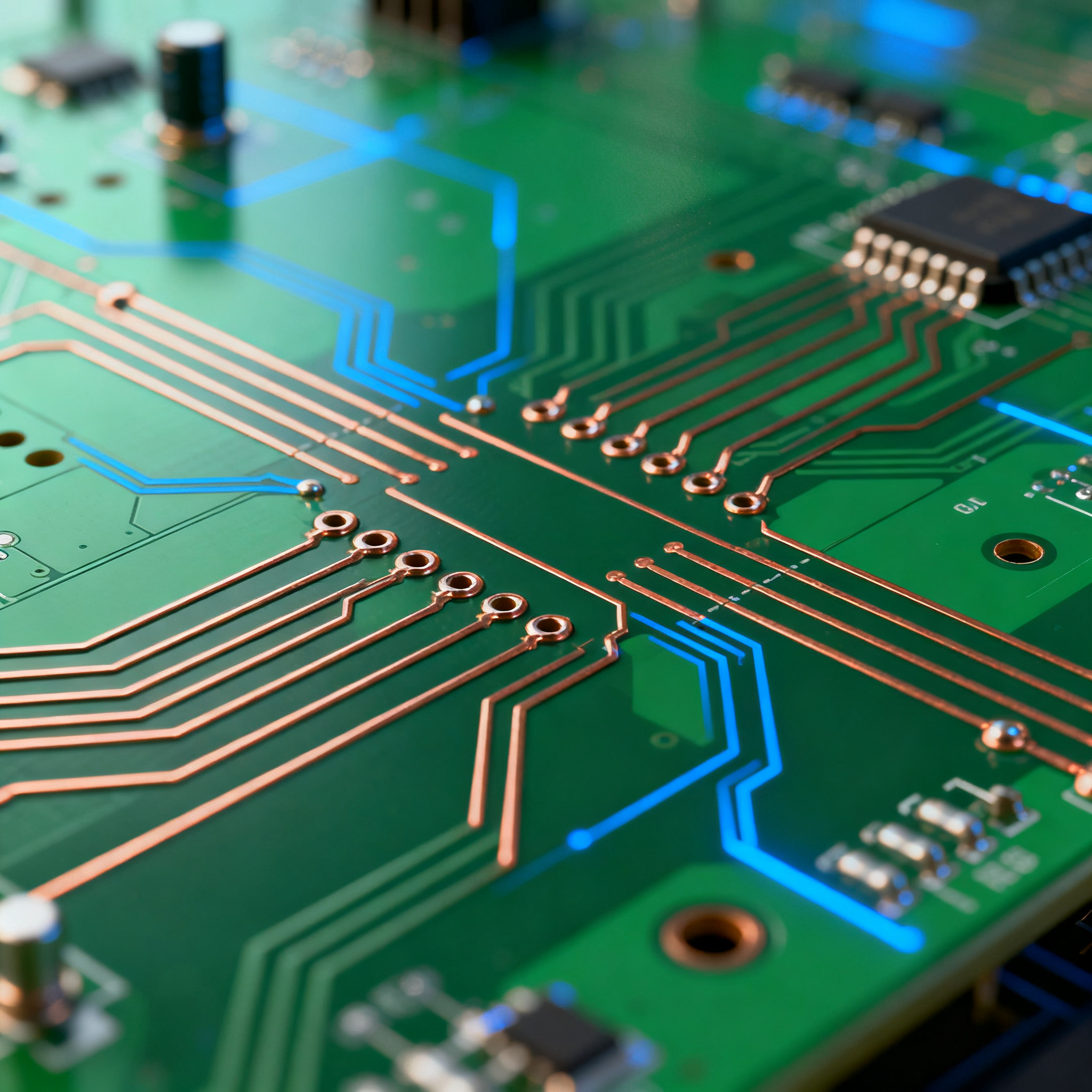
PCB Design for Electrical Performance: Key Techniques to Enhance Signal Integrity in RF Circuits
Introduction In the rapidly evolving world of electronics, RF circuits play a crucial role in wireless communication systems. Ensuring signal integrity in these circuits is paramount for optimal perfo...
Introduction
In the rapidly evolving world of electronics, RF circuits play a crucial role in wireless communication systems. Ensuring signal integrity in these circuits is paramount for optimal performance, especially in high-frequency applications. Signal integrity issues can lead to data loss, increased error rates, and reduced system reliability. This article delves into PCB design techniques that enhance the electrical performance of RF circuits, focusing on component specifications, datasheets, selection criteria, and application circuits.
Technical Overview
RF circuits are integral to modern communication systems, facilitating wireless data transmission. These circuits operate at high frequencies, making them susceptible to various signal integrity issues such as crosstalk, electromagnetic interference (EMI), and signal reflection. To combat these issues, PCB design for RF circuits requires meticulous planning and execution. Key techniques include proper impedance matching, strategic component placement, and the use of ground planes to minimize interference. Understanding the architecture of RF circuits and the principles of signal integrity is essential for designing effective PCBs that maintain high performance.
Detailed Specifications
When designing PCBs for RF circuits, understanding component specifications is crucial. These specifications guide the selection of appropriate integrated circuits (ICs) that meet the performance requirements of the application. Key specifications to consider include CPU speed, memory capacity, peripheral interfaces, power consumption, and package type. These factors influence the circuit's overall performance, reliability, and compatibility with other components.
| Specification | Details | Importance |
|---|---|---|
| CPU Speed | 1.2 GHz | Determines processing capability |
| Memory | 512 MB DDR4 | Essential for data handling |
| Peripherals | SPI, I2C, UART | Enables interfacing with other devices |
| Power Supply | 3.3V | Standard voltage level for ICs |
| Package Type | LQFP | Affects PCB layout design |
| Operating Temperature | -40°C to 85°C | Ensures reliability in varying conditions |
| Clock Frequency | 100 MHz | Impacts signal timing and processing |
| Data Rate | 1 Gbps | Defines the speed of data transmission |
| Power Consumption | 250 mW | Influences thermal management |
| Input/Output Pins | 40 | Determines connectivity options |
Key Takeaways from the Specifications
The specifications outlined in Table 1 highlight the critical parameters that influence the performance of RF circuits. CPU speed and memory are pivotal for processing and data handling, while peripheral interfaces such as SPI and I2C enable seamless communication with other components. The power supply voltage and package type are crucial for ensuring compatibility and ease of integration within the PCB design. Understanding these specifications allows designers to select components that meet the application's requirements, ensuring optimal performance and reliability.
| Parameter | Specification | Significance |
|---|---|---|
| Operating Voltage | 1.8V - 3.3V | Ensures compatibility with other components |
| Current Consumption | 50 mA | Affects power efficiency |
| Input Low Voltage | 0.8V max | Defines logic level thresholds |
| Input High Voltage | 2.0V min | Ensures signal integrity |
| Output Low Voltage | 0.4V max | Determines logic level output |
| Output High Voltage | 2.9V min | Ensures strong signal output |
| Propagation Delay | 5 ns | Impacts signal timing |
| Rise Time | 2 ns | Influences signal transition speed |
| Fall Time | 2 ns | Affects signal transition speed |
| Max Clock Frequency | 200 MHz | Determines data processing capability |
Practical Implications
The electrical characteristics in Table 2 provide insights into the performance and compatibility of RF circuit components. Operating voltage and current consumption are critical for ensuring power efficiency and compatibility with other system components. Input and output voltage levels define the logic thresholds necessary for robust signal integrity. Timing parameters like propagation delay and rise/fall times are crucial for maintaining signal timing and preventing data errors. These specifications guide engineers in designing circuits that meet performance criteria while minimizing power consumption and ensuring signal fidelity.
| Application | Configuration | Benefits |
|---|---|---|
| Wireless Communication | 2.4 GHz RF Module | Provides high-speed data transmission |
| IoT Devices | Low-power RF Transceiver | Enables energy-efficient data exchange |
| Satellite Communication | High-frequency RF Amplifier | Ensures long-distance signal clarity |
| Radar Systems | Wide-band RF Receiver | Offers precise target detection |
| Mobile Devices | Multi-band RF Front-end | Supports diverse communication standards |
| Automotive Systems | RF Sensor Module | Facilitates advanced driver-assistance systems |
| Industrial Automation | Robust RF Modem | Ensures reliable machine-to-machine communication |
Application Guidelines
The application comparison in Table 3 highlights the versatility of RF circuits across various domains. For wireless communication, utilizing a 2.4 GHz RF module ensures high-speed data transfer, while IoT devices benefit from low-power RF transceivers for energy efficiency. In satellite communication, high-frequency RF amplifiers provide clear signals over long distances. Each application has specific configuration needs, emphasizing the importance of selecting components that align with the desired use case. Understanding these applications assists engineers in designing tailored solutions that maximize performance and efficiency.
Design Considerations
Designing PCBs for RF circuits requires careful consideration of several factors to ensure optimal performance. Impedance matching is critical to minimize signal reflection and loss, necessitating precise trace width calculations and careful component selection. Ground planes and shielding are essential for reducing electromagnetic interference, while proper trace routing minimizes crosstalk and signal distortion. Thermal management is another crucial aspect, as RF components can generate significant heat during operation. By implementing effective heat dissipation techniques, designers can prevent overheating and ensure reliable circuit performance. Additionally, selecting components with appropriate environmental ratings ensures the PCB can withstand varying operating conditions.
Step-by-Step Implementation
- Define Requirements: Begin by outlining the specific requirements of the RF circuit, including frequency range, power levels, and application-specific needs.
- Select Components: Use datasheets and specifications to choose components that meet the defined requirements, focusing on parameters such as CPU speed, memory, and peripheral interfaces.
- Design Schematic: Create a detailed schematic diagram that includes all components and their connections, ensuring proper impedance matching and signal integrity.
- Layout Design: Design the PCB layout, paying careful attention to trace routing, ground plane placement, and component positioning to minimize interference and signal loss.
- Simulate Circuit: Use simulation tools to analyze the circuit's performance, identifying potential issues such as crosstalk or EMI, and make necessary adjustments to the design.
- Prototype and Test: Fabricate a prototype PCB and conduct thorough testing to verify the circuit's performance under real-world conditions, ensuring it meets all specifications.
- Iterate and Optimize: Based on testing results, make iterative improvements to the design to enhance performance, reliability, and manufacturability.
- Finalize Design: Once optimized, finalize the design and prepare for mass production, ensuring all documentation is complete and accurate.
Common Issues & Solutions
- Signal Reflection: Caused by impedance mismatches, this can be mitigated by ensuring proper trace width and using termination resistors.
- Electromagnetic Interference (EMI): Use ground planes and shielding to minimize EMI, and maintain adequate spacing between traces.
- Crosstalk: Route traces orthogonally and maintain sufficient separation to reduce crosstalk between adjacent signals.
- Thermal Management: Implement effective heat dissipation techniques such as heat sinks and thermal vias to prevent overheating.
- Component Selection: Ensure components are rated for the operating environment and are compatible with the circuit's requirements.
- Power Integrity: Use decoupling capacitors and proper power distribution techniques to maintain stable power levels across the circuit.
Applications & Use Cases
RF circuits find applications in a wide range of industries, from telecommunications to automotive systems. In wireless communication, RF circuits enable high-speed data transfer and reliable connectivity. IoT devices leverage these circuits for low-power, long-range communication, while satellite systems benefit from their ability to transmit signals over vast distances. In automotive applications, RF circuits facilitate advanced driver-assistance systems and vehicle-to-everything (V2X) communication. Industrial automation relies on RF circuits for robust machine-to-machine communication, ensuring efficient and reliable operation.
Selection & Sourcing Guide
When selecting components for RF circuits, it is essential to consider factors such as performance specifications, compatibility, and environmental ratings. Utilize resources like IC Online for sourcing components, ensuring they meet the required standards and are from reputable manufacturers. Comparing datasheets and consulting with suppliers can aid in making informed decisions, ensuring the selected components are suitable for the intended application.
FAQ
- What is signal integrity in RF circuits? Signal integrity refers to the quality and reliability of signals as they travel through a circuit, crucial for maintaining accurate data transmission.
- How can I minimize EMI in my PCB design? Use ground planes, shielding, and maintain adequate spacing between traces to reduce electromagnetic interference.
- What are the key considerations for component selection? Focus on specifications such as operating frequency, power consumption, and environmental ratings to ensure compatibility and performance.
- Why is impedance matching important? Impedance matching minimizes signal reflection and loss, ensuring optimal signal integrity in RF circuits.
- How do I manage thermal issues in RF circuits? Implement heat dissipation techniques like heat sinks and thermal vias to prevent overheating and maintain reliability.
- What tools can I use for PCB simulation? Software tools like SPICE and HFSS can simulate circuit performance and identify potential issues before fabrication.
- How do I ensure power integrity in my design? Use decoupling capacitors and proper power distribution techniques to maintain stable power levels.
- What are the advantages of using ground planes? Ground planes provide a low-impedance path for return currents, reducing EMI and improving signal integrity.
- How can I optimize trace routing? Keep traces short, maintain consistent widths, and avoid sharp bends to minimize signal loss and crosstalk.
- What is the role of RF circuits in IoT devices? RF circuits enable low-power, long-range communication, essential for connecting IoT devices to the network.
Conclusion
Ensuring signal integrity in RF circuits is essential for optimal performance in high-frequency applications. By understanding component specifications, employing effective PCB design techniques, and selecting the right components, engineers can create reliable and efficient RF systems. This article has provided insights into the key specifications, practical design considerations, and common issues associated with RF circuit design, offering a comprehensive guide for enhancing electrical performance and signal integrity.