Mastering the SMT Assembly Process Flow: A Step-by-Step Guide for Efficient Production
Mastering the SMT Assembly Process Flow: A Step-by-Step Guide for Efficient Production table { border-collapse: collapse; width: 100%; margin: 20px 0; } th, td { border: 1px solid #ccc; padding: 8px; ...
Introduction
In the ever-evolving electronics industry, Surface Mount Technology (SMT) is a critical process for assembling printed circuit boards (PCBs) efficiently. As demand for compact, high-performance electronic devices grows, mastering SMT assembly becomes essential for manufacturers. This guide provides a comprehensive overview of the SMT process, focusing on component specifications, selection criteria, and application circuits, crucial for effective production. By understanding these elements, engineers and manufacturers can enhance product reliability, reduce costs, and meet stringent industry standards.
Technical Overview
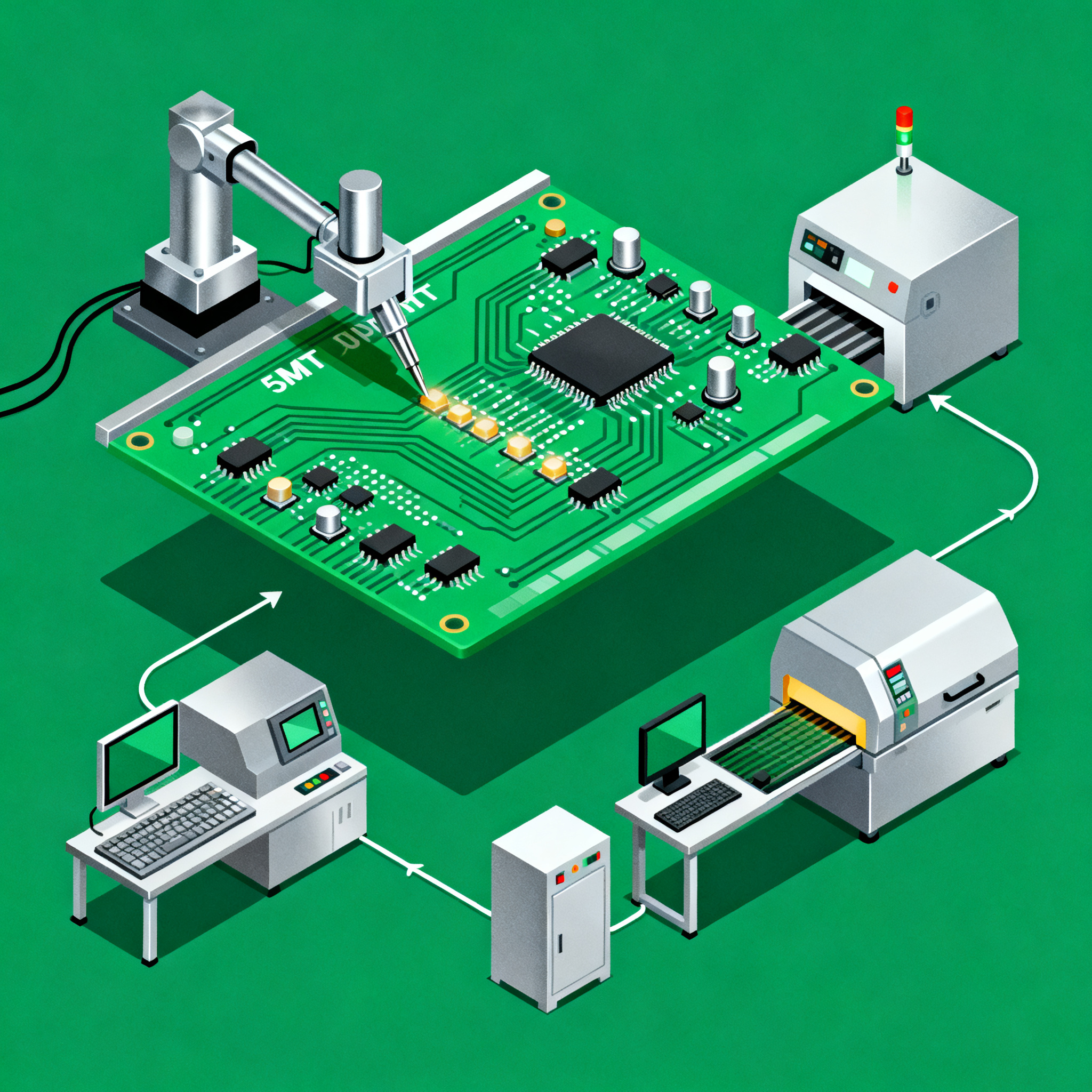
The SMT assembly process involves mounting electronic components directly onto the surface of PCBs. This method contrasts with through-hole technology, which requires component leads to pass through board holes. SMT offers advantages such as reduced size, weight, and production costs, making it the preferred choice for modern electronics. Key steps in the SMT process include solder paste application, component placement, reflow soldering, and inspection. Each stage requires precision and adherence to standards like IPC-A-610 to ensure quality and performance.
Understanding component specifications is crucial in the SMT process. Specifications include CPU speed, memory, peripherals, power consumption, and packaging, which influence the design and functionality of the final product. Datasheets provide detailed information, guiding engineers in selecting suitable components. Additionally, application circuits highlight how components function within a system, aiding in efficient design and troubleshooting.
Detailed Specifications
Component specifications are vital for designing efficient electronic systems. They dictate the performance, compatibility, and reliability of the final product. Key specifications include CPU speed, memory capacity, peripheral interfaces, power requirements, and packaging type. Understanding these parameters helps engineers choose the right components and optimize circuit designs for specific applications.
| Specification | Details | Notes |
|---|---|---|
| CPU Speed | 1.2 GHz | High performance for complex tasks |
| Memory | 4 GB DDR4 | Sufficient for multitasking |
| Peripherals | USB, HDMI, Ethernet | Standard connectivity options |
| Power | 5V, 2A | Efficient power consumption |
| Package | LQFP-64 | Compact and reliable |
| Operating Temperature | -40°C to 85°C | Suitable for various environments |
| Storage Temperature | -55°C to 125°C | Wide storage range |
| ESD Protection | 2 kV | Enhanced durability |
| MTBF | 1,000,000 hours | Long operational life |
| RoHS Compliance | Yes | Environmentally friendly |
Key Takeaways from the Specifications
The specifications table provides a detailed look at the essential parameters of electronic components used in SMT assembly. The CPU speed of 1.2 GHz ensures high performance, making it suitable for demanding applications. With 4 GB DDR4 memory, the system can handle multitasking efficiently. The inclusion of common peripherals like USB, HDMI, and Ethernet ensures versatility in connectivity, while the power requirement of 5V, 2A highlights the component's energy efficiency. The LQFP-64 package offers a compact form factor, ideal for reducing PCB space. Understanding these specifications helps in selecting the right components for specific applications, ensuring optimal performance and reliability.
| Electrical Characteristic | Value | Notes |
|---|---|---|
| Supply Voltage | 3.3V | Standard operating voltage |
| Current Consumption | 500 mA | Low power usage |
| Input Voltage Range | 2.7V - 3.6V | Flexible input range |
| Output Current | 100 mA | Sufficient for driving peripherals |
| Clock Frequency | 100 MHz | High-speed operation |
| Input Impedance | 10 kΩ | Standard input impedance |
| Output Impedance | 50 Ω | Standard output impedance |
| Propagation Delay | 5 ns | Fast signal processing |
| Rise/Fall Time | 2 ns | Quick transition times |
| Operating Frequency Range | 1 MHz - 500 MHz | Wide frequency range |
| Thermal Resistance | 50°C/W | Efficient heat dissipation |
Practical Implications
The electrical characteristics table highlights the critical parameters that affect component performance in real-world applications. A supply voltage of 3.3V is typical for modern electronics, ensuring compatibility with a wide range of devices. The low current consumption of 500 mA supports energy-efficient designs, while the output current of 100 mA is adequate for driving standard peripherals. The clock frequency of 100 MHz and propagation delay of 5 ns ensure high-speed data processing, essential for applications requiring quick response times. These characteristics are crucial for designing efficient, reliable systems that meet industry standards.
| Application | Configuration | Benefits |
|---|---|---|
| Consumer Electronics | Standard MCU configuration | Cost-effective, energy-efficient |
| Industrial Automation | Robust I/O setup | Reliable, high performance |
| Automotive Systems | Enhanced ESD protection | Durable, long lifespan |
| Medical Devices | Low power consumption | Safe, reliable operation |
| Telecommunications | High-speed data processing | Fast, efficient communication |
| Home Automation | Wireless connectivity | Convenience, control |
| Wearable Devices | Compact packaging | Portable, user-friendly |
| Smart Grid | Secure data transmission | Reliable, safe |
Application Guidelines
The application comparison table illustrates how different configurations of components cater to various industry needs. In consumer electronics, a standard MCU configuration offers a balance of cost and efficiency. Industrial automation benefits from a robust I/O setup, ensuring reliable and high-performance operations. Automotive systems require enhanced ESD protection for durability and longevity. In medical devices, low power consumption is crucial for safety and reliability. Telecommunications demand high-speed data processing for efficient communication. Understanding these configurations and benefits aids in selecting the most suitable components for specific applications, enhancing overall product performance.
Design Considerations
Effective design in the SMT assembly process requires careful consideration of several factors. First, component placement is critical; it impacts signal integrity and thermal performance. Ensuring that components are placed according to manufacturer guidelines and industry standards, such as those from IPC, can minimize potential issues. Additionally, selecting appropriate solder paste and stencil design is essential for achieving reliable solder joints. Engineers must also account for thermal management, using heat sinks or vias to dissipate heat efficiently.
Designers should consider the PCB layout, ensuring trace widths and spacing adhere to design rules provided by PCBWay. This helps prevent electrical interference and ensures signal integrity. Another critical aspect is testing and inspection; using automated optical inspection (AOI) and in-circuit testing (ICT) can identify issues early in the production cycle, reducing rework and improving yield.
Finally, compliance with environmental and safety standards, such as RoHS and ESD protection, is crucial. These considerations not only enhance product reliability but also ensure adherence to regulatory requirements, making the product market-ready.
Step-by-Step Implementation
- Design Preparation: Begin with a thorough analysis of the project requirements and specifications. Utilize design software to create a schematic and PCB layout, ensuring adherence to industry standards and guidelines.
- Solder Paste Application: Apply solder paste to the PCB using a stencil. Ensure even distribution to avoid defects during the reflow process. Automated dispensers can enhance precision and efficiency.
- Component Placement: Use pick-and-place machines to accurately position components on the PCB. Verify component orientation and alignment to prevent assembly errors.
- Reflow Soldering: Transfer the PCB to a reflow oven where the solder paste is melted, creating solid connections between components and the PCB. Monitor temperature profiles to avoid overheating.
- Inspection and Testing: Conduct automated optical inspection (AOI) to detect any soldering defects or misplaced components. Perform in-circuit testing (ICT) to verify electrical performance.
- Rework and Repair: Address any defects identified during inspection. Use hot-air rework stations to remove and replace faulty components without damaging the PCB.
- Final Assembly: Integrate all PCB assemblies into the final product. Ensure all connectors, housings, and interfaces are securely attached and functioning correctly.
- Quality Assurance: Perform a final quality check to ensure the product meets all specifications and standards. Document any deviations and corrective actions taken.
Common Issues & Solutions
- Solder Bridging: Occurs when excess solder creates a connection between adjacent pads. Solution: Adjust stencil design and solder paste volume.
- Component Misalignment: Misplaced components can lead to functionality issues. Solution: Calibrate pick-and-place machines and ensure proper tape and reel orientation.
- Insufficient Solder Wetting: Results in weak solder joints. Solution: Optimize reflow profiles and ensure proper solder paste storage.
- Thermal Issues: Excessive heat can damage components. Solution: Use thermal pads and heat sinks to manage heat dissipation.
- ESD Damage: Static discharge can destroy sensitive components. Solution: Implement ESD control measures, such as wrist straps and conductive mats.
- Delamination: Occurs when PCB layers separate. Solution: Ensure proper lamination techniques and storage conditions.
Applications & Use Cases
SMT assembly is widely used across various industries due to its efficiency and reliability. In consumer electronics, it enables the production of compact devices such as smartphones and tablets. Industrial automation systems benefit from SMT's ability to produce high-density PCBs required for complex control systems. In the automotive industry, SMT is used for engine control units and infotainment systems, where space and reliability are crucial. Medical devices, such as portable monitors and diagnostic equipment, leverage SMT for its precision and miniaturization capabilities. In telecommunications, SMT supports the production of high-speed networking equipment, essential for modern communication infrastructures.
Selection & Sourcing Guide
When selecting components for SMT assembly, consider factors such as performance requirements, environmental conditions, and compliance with industry standards. Utilize resources like IC Online to source components efficiently. Ensure that suppliers provide comprehensive datasheets and support for the components they offer. Evaluate multiple suppliers to ensure competitive pricing and availability, and consider working with authorized distributors to reduce the risk of counterfeit components.
FAQ
- What is SMT assembly? SMT (Surface Mount Technology) assembly is a method of mounting electronic components directly onto the surface of a PCB, offering advantages in size, weight, and cost over traditional through-hole technology.
- Why are component specifications important? Specifications determine a component's performance, compatibility, and reliability, guiding engineers in selecting suitable components for efficient design.
- How can I prevent solder bridging? Adjusting stencil design and solder paste volume can help prevent solder bridging, a common defect in SMT assembly.
- What role does reflow soldering play in SMT? Reflow soldering melts the solder paste to form connections between components and the PCB, ensuring electrical and mechanical integrity.
- How do I manage thermal issues in SMT design? Use thermal pads, heat sinks, and vias to dissipate heat effectively, preventing damage to components and ensuring reliable operation.
- What standards should I follow for SMT assembly? Adhere to IPC standards, such as IPC-A-610, for quality and reliability in PCB design and assembly.
- How do I choose the right components for my application? Consider specifications such as CPU speed, memory, and power requirements, and evaluate datasheets for performance and compatibility.
- What are common inspection methods in SMT assembly? Automated optical inspection (AOI) and in-circuit testing (ICT) are commonly used to identify defects and verify electrical performance.
- How can I ensure ESD protection during assembly? Implement ESD control measures like wrist straps, conductive mats, and proper handling procedures to protect sensitive components.
- What are the benefits of using SMT in industrial automation? SMT provides high-density PCB designs, essential for complex control systems, ensuring reliability and performance in industrial applications.
Conclusion
Mastering the SMT assembly process is essential for producing high-quality electronic devices efficiently. By understanding component specifications, electrical characteristics, and application configurations, engineers can design reliable, cost-effective systems. Adhering to industry standards and implementing effective design and inspection practices enhances product performance and compliance. As the electronics industry continues to advance, staying informed about the latest SMT techniques and technologies is crucial for maintaining a competitive edge.