Mastering PCBA Design Rules: Essential Guidelines for Reliable Circuit Performance
Mastering PCBA Design Rules: Essential Guidelines for Reliable Circuit Performance Introduction In today's fast-paced electronics industry, mastering Printed Circuit Board Assembly (PCBA) design rules...
Introduction
In today's fast-paced electronics industry, mastering Printed Circuit Board Assembly (PCBA) design rules is essential for ensuring reliable circuit performance. With the increasing complexity of electronic devices, understanding the nuances of component specifications, datasheets, selection criteria, and application circuits becomes crucial. This article delves into the heart of PCBA design, offering detailed insights into the specifications and standards that underpin the creation of efficient and dependable electronic assemblies. By adhering to industry standards like those from IPC, designers can significantly enhance the durability and functionality of their circuits.
Technical Overview
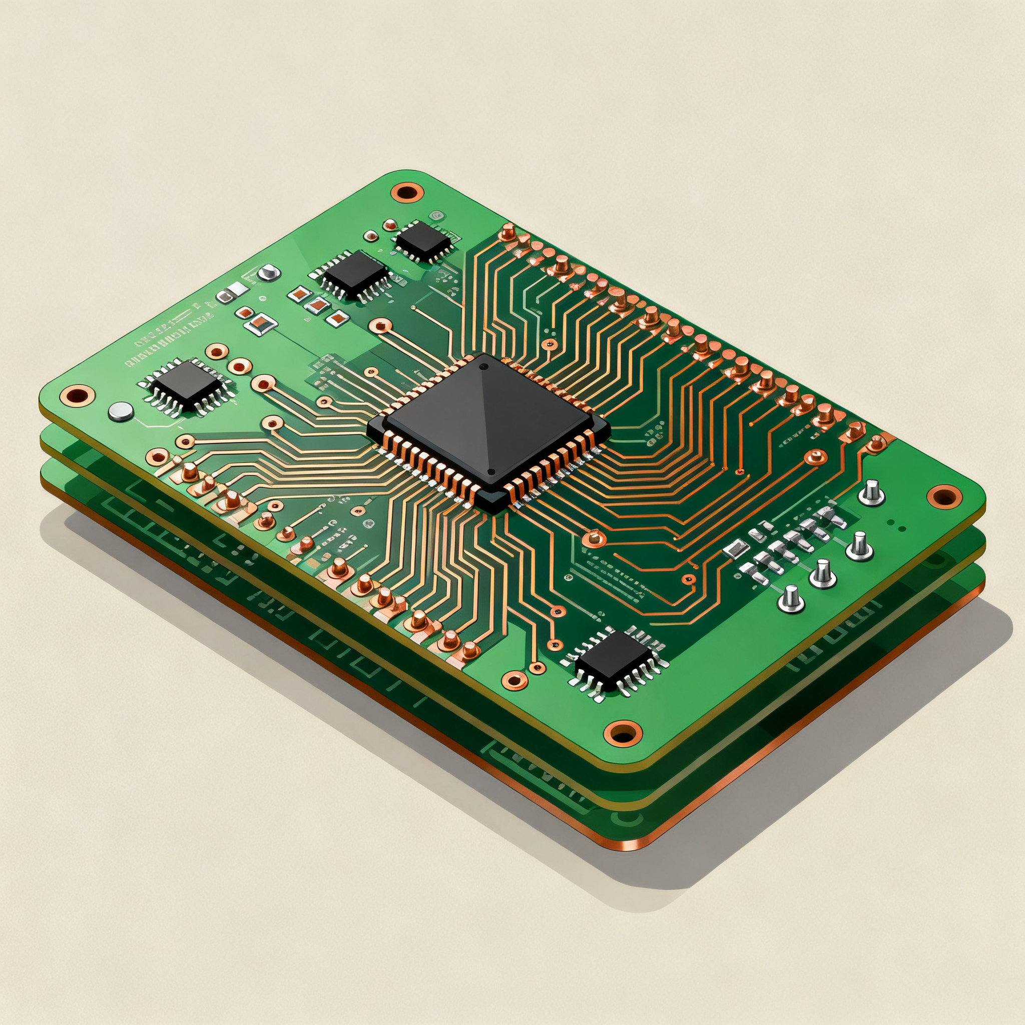
PCBA design involves integrating various electronic components onto a printed circuit board (PCB) to create a functional electronic device. The process requires a deep understanding of core concepts such as signal integrity, thermal management, and component placement. The architecture of a PCBA is defined by the layout and interconnections of components, which must adhere to specific design rules to ensure optimal performance. Key principles include minimizing electromagnetic interference (EMI), ensuring adequate trace width for current carrying capacity, and maintaining proper spacing between components to prevent shorts and enhance thermal dissipation. These principles are guided by standards like IPC-A-610 and IPC-2221, which provide comprehensive guidelines for PCB design and assembly.
Detailed Specifications
Specifications play a pivotal role in PCBA design, as they define the operational limits and capabilities of a circuit. Key specifications include voltage and current ratings, component tolerances, and environmental conditions. These parameters are critical in ensuring that a circuit performs reliably under various operating conditions. Understanding these specifications helps designers make informed decisions when selecting components and designing circuits for specific applications.
| Parameter | Specification | Comments |
|---|---|---|
| Voltage Rating | 3.3V - 12V | Common range for digital circuits |
| Current Rating | 0.5A - 10A | Depends on trace width and application |
| Power Rating | 1W - 100W | Varies with component and use case |
| Temperature Range | -40°C to 85°C | Standard industrial temperature range |
| Component Tolerance | ±5% | Typical for resistors and capacitors |
| Dielectric Constant | 4.5 | Affects signal speed and impedance |
| Trace Width | 0.15mm - 0.5mm | Determines current capacity |
| Layer Count | 2 - 16 layers | More layers for complex designs |
| Impedance Control | 50Ω ±10% | Critical for high-speed designs |
| Surface Finish | ENIG, HASL | Affects solderability and reliability |
| RoHS Compliance | Yes | Ensures environmental safety |
Key Takeaways from the Specifications
The specifications outlined in the table are fundamental to ensuring the reliability and performance of a PCBA. Voltage and current ratings determine the operational limits of the circuit, while power ratings indicate the capacity of the circuit to handle energy. The temperature range is crucial for determining the suitability of a circuit for various environmental conditions. Component tolerances and dielectric constants impact the precision and performance of the circuit. Trace width and layer count are essential for managing current flow and accommodating complex designs. Impedance control is critical for maintaining signal integrity in high-speed applications. Understanding these specifications allows designers to select appropriate components and design circuits that meet the required performance standards.
| Metric | Value | Importance |
|---|---|---|
| Signal Integrity | High | Ensures accurate data transmission |
| Thermal Conductivity | 0.8 W/mK | Important for heat dissipation |
| Frequency Range | DC - 3GHz | Defines application scope |
| Noise Margin | 1V | Critical for digital circuits |
| Power Efficiency | 85% | Reduces energy consumption |
| EMI Shielding | Effective | Prevents interference |
| Reliability (MTBF) | 100,000 hours | Indicates longevity |
| Switching Speed | 1ns | Important for timing-critical applications |
| Thermal Resistance | 10°C/W | Affects cooling requirements |
Practical Implications
The performance metrics highlighted in the table provide insights into the operational efficiency and reliability of a PCBA. Signal integrity is paramount for ensuring accurate data transmission, especially in high-frequency applications. Thermal conductivity and resistance are crucial for effective heat management, which is vital for maintaining circuit stability and preventing overheating. The frequency range defines the scope of applications the circuit can support, while the noise margin is essential for ensuring robust digital signal processing. Power efficiency is a key consideration for reducing energy consumption and enhancing battery life in portable devices. EMI shielding and reliability metrics like MTBF indicate the circuit's ability to operate without interference and its expected lifespan. These metrics guide designers in optimizing circuit performance and ensuring long-term reliability.
| Use Case | Configuration | Notes |
|---|---|---|
| Consumer Electronics | 4-layer PCB | Common for smartphones and tablets |
| Automotive | 8-layer PCB | Required for complex systems |
| Industrial Control | 6-layer PCB | Suitable for robust applications |
| Medical Devices | 10-layer PCB | Ensures high reliability |
| Telecommunications | 12-layer PCB | Handles high data rates |
| Aerospace | 16-layer PCB | Designed for harsh environments |
| IoT Devices | 2-layer PCB | Cost-effective for simple designs |
Application Guidelines
The application matrix provides a roadmap for selecting the appropriate PCB configuration based on the specific use case. Consumer electronics typically utilize 4-layer PCBs to balance performance and cost, while automotive applications require 8-layer PCBs to manage the complexity of modern vehicle systems. Industrial control systems benefit from 6-layer PCBs, offering robustness and reliability. Medical devices demand high reliability, often necessitating 10-layer PCBs. Telecommunications and aerospace applications, which operate in demanding environments and require high data rates, use 12-layer and 16-layer PCBs, respectively. IoT devices, on the other hand, often use 2-layer PCBs for cost-effective, simple designs. Understanding these configurations helps designers tailor their designs to meet the specific requirements of each application, ensuring optimal performance and reliability.
Design Considerations
When designing a PCBA, several key considerations must be taken into account to ensure optimal performance and reliability. First, component placement is critical; components should be arranged to minimize trace lengths and reduce potential EMI. The choice of materials, such as the substrate and solder mask, can significantly impact thermal performance and mechanical stability. Designers must also consider the thermal management of the PCB, employing techniques such as heat sinks, thermal vias, and careful trace routing to manage heat dissipation effectively.
Another important aspect is impedance matching, especially in high-frequency applications, to minimize signal reflection and loss. Designers should also pay attention to power distribution networks (PDNs) to ensure stable power delivery throughout the circuit. This involves designing adequate power and ground planes and using decoupling capacitors effectively.
Furthermore, adherence to industry standards, such as those from the IPC, is essential for ensuring quality and reliability. Following these guidelines helps in achieving consistent results and facilitates easier troubleshooting and maintenance. Additionally, designers should incorporate design for manufacturability (DFM) principles to streamline the production process and reduce costs.
Step-by-Step Implementation
- Define Requirements: Start by clearly defining the project requirements, including performance specifications, environmental conditions, and any regulatory standards that must be met.
- Component Selection: Choose components based on their specifications, cost, and availability. Refer to datasheets and application notes to ensure compatibility with the desired circuit performance.
- Schematic Design: Create a detailed schematic diagram that includes all components, their interconnections, and any necessary annotations or notes.
- PCB Layout: Using PCB design software, lay out the components on the board. Pay attention to trace routing, component placement, and thermal management features.
- Simulation and Analysis: Perform simulations to verify the design's performance, checking for issues such as signal integrity, thermal performance, and EMI.
- Prototype Fabrication: Once the design is validated, proceed with fabricating a prototype PCB. This involves sending the design files to a PCB manufacturer.
- Assembly and Testing: Assemble the prototype, soldering components onto the PCB. Conduct thorough testing to ensure the circuit meets all performance criteria.
- Iteration and Finalization: Based on test results, make any necessary design adjustments. Finalize the design for mass production, ensuring all documentation is complete and accurate.
Common Issues & Solutions
- Component Mismatch: Ensure component specifications align with design requirements by cross-referencing datasheets.
- Signal Integrity Problems: Use proper trace routing techniques and impedance matching to maintain signal quality.
- Thermal Management Challenges: Incorporate thermal vias and heat sinks to manage heat dissipation effectively.
- EMI Interference: Implement shielding and proper grounding techniques to minimize electromagnetic interference.
- Manufacturing Defects: Follow DFM guidelines and perform thorough inspections to reduce production errors.
- Power Distribution Issues: Design robust PDNs with adequate decoupling capacitors to ensure stable power delivery.
Applications & Use Cases
PCBA design is foundational to a wide range of applications across various industries. In consumer electronics, PCBs are integral to devices such as smartphones, tablets, and laptops, enabling complex functionalities in compact form factors. In the automotive industry, PCBs are used in systems ranging from infotainment and navigation to advanced driver assistance systems (ADAS) and engine control units (ECUs). Medical devices rely on PCBs for critical applications like diagnostic equipment, patient monitoring systems, and implantable devices, where reliability is paramount. In telecommunications, PCBs facilitate high-speed data transmission and networking in routers, switches, and base stations. Aerospace applications demand PCBs that can withstand extreme conditions, supporting avionics, communication systems, and navigation equipment. Finally, the growing Internet of Things (IoT) sector leverages PCBs to connect and control a myriad of smart devices, from home automation systems to industrial sensors.
Selection & Sourcing Guide
When selecting and sourcing components for a PCBA, it is essential to consider factors such as availability, lead times, and cost. Utilize online resources like IC Online to compare component options and check for stock levels and pricing. Additionally, consider working with reputable distributors and manufacturers who offer quality assurance and support for their products. Establishing strong relationships with suppliers can help streamline the sourcing process and ensure timely delivery of components, which is critical for maintaining project timelines and budget.
FAQ
- What are the key considerations in PCBA design? Critical considerations include component placement, thermal management, impedance matching, and adherence to industry standards.
- How do I select components for my PCBA? Choose components based on their specifications, datasheet information, and compatibility with your design requirements.
- What is the importance of IPC standards? IPC standards provide guidelines for PCB design and assembly, ensuring quality and reliability in electronic assemblies.
- How can I manage thermal issues in my design? Use thermal vias, heat sinks, and proper trace routing to effectively manage heat dissipation.
- What tools are available for PCB design? Popular tools include Altium Designer, Eagle, and KiCad, which offer features for schematic capture, layout, and simulation.
- How do I ensure signal integrity in high-speed designs? Implement proper trace routing, impedance matching, and use of differential pairs to maintain signal quality.
- What are common manufacturing defects to watch out for? Common defects include solder bridges, misaligned components, and insufficient solder joints. Inspect thoroughly to identify and rectify these issues.
- What is the role of a power distribution network (PDN)? A PDN ensures stable power delivery throughout the circuit, essential for reliable operation.
- How can I reduce EMI in my design? Use shielding, proper grounding, and layout techniques to minimize electromagnetic interference.
- What are the benefits of a multilayer PCB? Multilayer PCBs offer increased routing density, improved signal integrity, and better power distribution, making them ideal for complex designs.
Conclusion
Mastering PCBA design rules is essential for creating reliable and high-performance electronic assemblies. By understanding component specifications, performance metrics, and application guidelines, designers can make informed decisions that enhance circuit functionality and longevity. Adhering to industry standards and employing best practices in design and manufacturing ensures that PCBA projects meet the highest quality and reliability standards. As the electronics industry continues to evolve, staying abreast of the latest design techniques and technologies will be crucial for success.