Mastering PCB Layout Design for EMI Compliance: Essential Techniques for High-Performance Circuits
Mastering PCB Layout Design for EMI Compliance table { border-collapse: collapse; width: 100%; margin: 20px 0; } th, td { border: 1px solid #ddd; padding: 8px; } th { background: #f0f0f0; } Introducti...
Introduction
In the ever-evolving world of electronics, ensuring electromagnetic interference (EMI) compliance in PCB layout design is crucial for the performance and reliability of high-frequency circuits. With the growing complexity of electronic devices, achieving EMI compliance is not just about adhering to regulatory standards but also about enhancing the device's functionality and user experience. This article delves into the essential techniques and considerations necessary for mastering PCB layout design with a focus on EMI compliance, ensuring your designs meet the highest performance standards.
Technical Overview
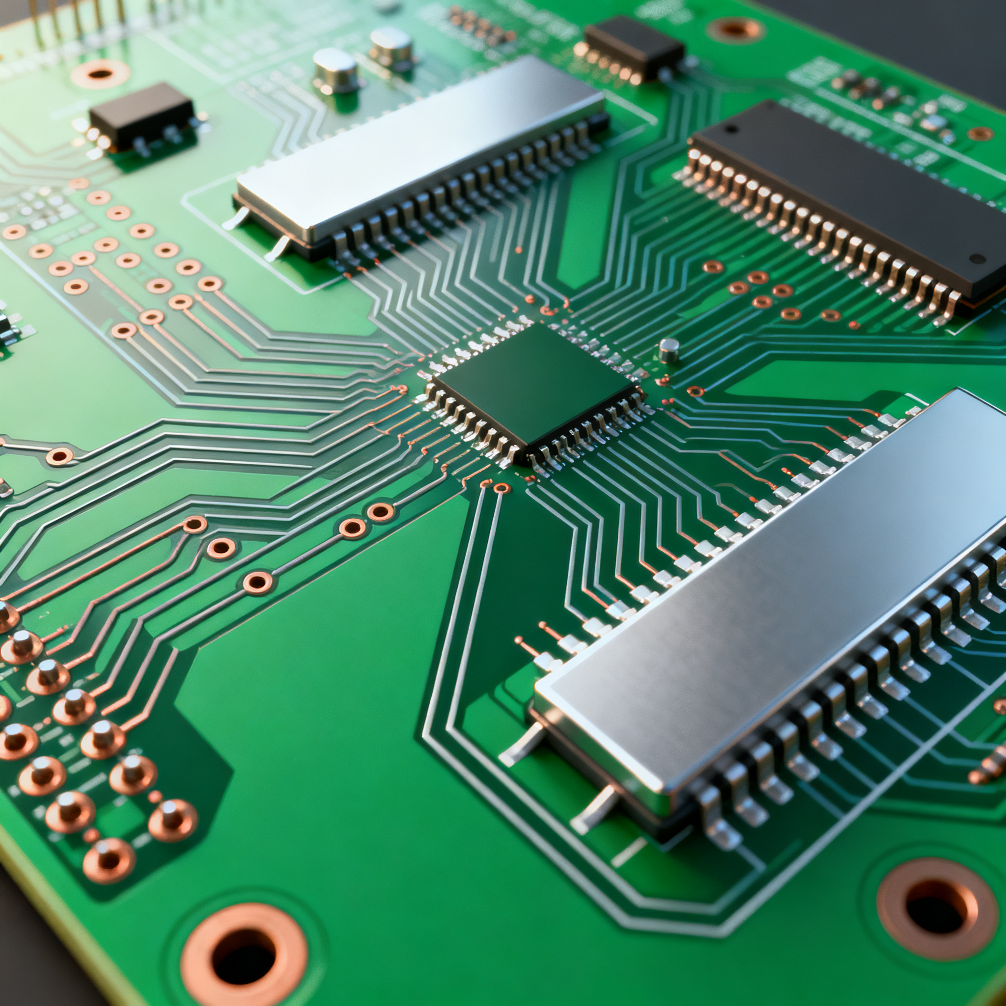
PCB layout design for EMI compliance involves understanding the intricate balance between signal integrity, power distribution, and electromagnetic compatibility. The core principles focus on minimizing interference through strategic component placement, routing, and grounding techniques. Key architectural elements include the use of decoupling capacitors, controlled impedance traces, and multilayer stack-ups. The aim is to reduce radiated and conducted emissions while maintaining signal integrity. This requires a thorough understanding of the electromagnetic spectrum, the use of simulation tools, and adherence to industry standards like those outlined by the IPC.
Detailed Specifications
In PCB design, understanding component specifications is paramount for ensuring EMI compliance. Key parameters such as impedance, dielectric constant, and thermal ratings play a critical role. These specifications help designers select the right materials and components that will minimize EMI and ensure reliable circuit performance.
| Parameter | Specification | Notes |
|---|---|---|
| Impedance | 50 Ohms | Standard for RF applications |
| Dielectric Constant | 4.5 | FR-4 material |
| Thermal Conductivity | 0.3 W/mK | Ensures heat dissipation |
| Layer Count | 4 Layers | Supports signal integrity |
| Trace Width | 0.15 mm | For controlled impedance |
| Operating Temperature | -40°C to 85°C | Wide temperature range |
| Voltage Rating | 5V DC | Common for low power circuits |
| Current Rating | 1A | Suitable for most applications |
| Surface Finish | HASL | Cost-effective option |
| Solder Mask Color | Green | Standard color |
| Board Thickness | 1.6 mm | Standard for durability |
Key Takeaways from the Specifications
The specifications outlined in Table 1 highlight the critical parameters necessary for designing PCBs with EMI compliance in mind. The impedance of 50 Ohms is standard for RF applications, ensuring optimal signal transmission. The dielectric constant and thermal conductivity are crucial for maintaining signal integrity and managing heat dissipation respectively. The layer count and trace width support controlled impedance, essential for minimizing electromagnetic interference. Understanding these parameters allows designers to make informed decisions when selecting materials and components, ultimately leading to more reliable and compliant PCB designs.
| Metric | Value | Significance |
|---|---|---|
| Signal Rise Time | 0.5 ns | Fast switching speed |
| Propagation Delay | 1.2 ns | Low latency |
| Crosstalk | -30 dB | Minimized interference |
| Insertion Loss | 0.5 dB | Low loss across traces |
| Return Loss | -20 dB | Improved signal reflection |
| Thermal Resistance | 35°C/W | Effective heat management |
| Power Dissipation | 500 mW | Handles power efficiently |
| Junction Temperature | 125°C | High thermal limit |
| ESD Protection | 8 kV | Robust against electrostatic discharge |
Practical Implications
The performance metrics in Table 2 provide insight into the electrical and thermal characteristics of the PCB design. Fast signal rise times and low propagation delays are vital for high-speed applications. Metrics like crosstalk and insertion loss indicate how well the design minimizes interference and signal loss. The thermal resistance and power dissipation values are crucial for ensuring that the board can manage heat effectively, preventing thermal-related failures. These metrics guide engineers in optimizing their designs for both performance and compliance, ultimately leading to more robust and reliable circuits.
| Application | Configuration | Notes |
|---|---|---|
| RF Communication | 2-Layer Board | For simple RF circuits |
| IoT Devices | 4-Layer Board | Improved signal integrity |
| Automotive Systems | 6-Layer Board | Enhanced EMI shielding |
| Consumer Electronics | 4-Layer Board | Cost-effective design |
| Industrial Controls | 8-Layer Board | Robust against interference |
| Medical Equipment | 6-Layer Board | Critical for low noise |
| High-Frequency Modules | 10-Layer Board | Maximum performance |
Application Guidelines
Table 3 outlines various applications and their recommended PCB configurations, highlighting the importance of selecting the right board setup for specific use cases. For instance, RF communication often uses a simple 2-layer board, while more complex IoT devices benefit from a 4-layer configuration to improve signal integrity. Automotive and industrial applications may require more layers for enhanced EMI shielding and robustness against interference. Understanding these configurations helps engineers tailor their designs to meet specific application needs, ensuring both performance and compliance.
Design Considerations
When designing a PCB for EMI compliance, several practical guidelines should be followed. Firstly, component placement is crucial; sensitive components should be placed away from potential sources of interference. Ground planes should be used extensively to provide a low-impedance path to ground, reducing the potential for EMI. Additionally, trace routing should minimize loop areas and avoid sharp angles, which can act as antennas for EMI. The use of decoupling capacitors near power pins can help reduce power supply noise. Furthermore, ensuring that all traces have controlled impedance is critical for high-speed signals to prevent reflections and signal degradation. Finally, simulation tools should be utilized to predict EMI performance and make necessary adjustments before manufacturing.
Step-by-Step Implementation
- Initial Design Planning: Begin by defining the PCB's functional requirements and constraints. Consider the operating environment, such as temperature and humidity, which can affect EMI.
- Component Selection: Choose components with appropriate specifications for EMI compliance. Refer to datasheets for parameters like impedance and thermal ratings.
- Schematic Design: Develop a schematic that outlines the electrical connections and signal paths. Pay attention to power distribution and grounding strategies.
- PCB Layout: Place components strategically to minimize interference. Use ground planes and decoupling capacitors effectively.
- Routing: Route traces with controlled impedance, keeping them short and avoiding sharp bends. Ensure differential pairs are matched.
- Simulation and Analysis: Use simulation tools to analyze the design for potential EMI issues. Adjust layout and components based on results.
- Prototyping: Manufacture a prototype board and conduct EMI testing. Identify and address any compliance issues.
- Final Design Adjustments: Make necessary changes based on prototype testing and re-evaluate the design to ensure compliance.
Common Issues & Solutions
Designing for EMI compliance can present several challenges. One common issue is excessive radiated emissions, often solved by improving grounding and shielding. Signal integrity problems, such as reflections, can be addressed by optimizing trace impedance and using termination resistors. Power supply noise can be reduced with additional decoupling capacitors and careful routing of power traces. Crosstalk between adjacent traces can be minimized by increasing trace spacing and using guard traces. Thermal management issues, which can exacerbate EMI problems, are often resolved by enhancing heat dissipation with thermal vias and heat sinks. By understanding and addressing these issues, designers can improve both EMI compliance and overall circuit performance.
Applications & Use Cases
EMI-compliant PCB designs are critical in various industries. In telecommunications, they ensure reliable data transmission and reception. Automotive applications rely on EMI compliance to prevent interference with onboard electronics and safety systems. In the medical field, low-noise designs are essential for accurate diagnostic equipment. Consumer electronics benefit from reduced interference, improving user experience and device reliability. Industrial controls require robust designs to function in harsh environments with minimal downtime. By focusing on EMI compliance, engineers can develop products that meet industry standards and perform reliably in real-world applications.
Selection & Sourcing Guide
Selecting the right components for EMI-compliant PCB design involves careful consideration of specifications and datasheets. Engineers should refer to resources like IC Online for a wide range of components and detailed specifications. It's important to source components from reputable suppliers to ensure quality and reliability. Additionally, working with PCB manufacturers that adhere to IPC standards can help ensure that the final product meets both design and compliance requirements.
FAQ
- What is EMI compliance? EMI compliance ensures that electronic devices do not emit or are susceptible to electromagnetic interference, meeting regulatory standards.
- Why is PCB layout important for EMI? The layout affects signal integrity and electromagnetic compatibility, influencing a device's ability to perform reliably.
- How do ground planes reduce EMI? Ground planes provide a low-impedance path to ground, minimizing loop areas and reducing potential interference.
- What role do decoupling capacitors play? They reduce power supply noise and stabilize voltage levels, crucial for minimizing EMI.
- How can simulation tools aid in EMI design? They allow designers to predict and analyze EMI performance, enabling early detection and correction of issues.
- What are common EMI testing methods? Testing methods include radiated emissions, conducted emissions, and susceptibility testing to ensure compliance.
- Can EMI be completely eliminated? While EMI cannot be entirely eliminated, it can be minimized to acceptable levels through careful design and testing.
- What is the impact of trace impedance on EMI? Controlled impedance prevents signal reflections, improving signal integrity and reducing EMI.
- Why is component placement critical? Strategic placement minimizes interference and optimizes performance by reducing loop areas and potential coupling.
- How does board layer count affect EMI? More layers can provide better shielding and separation of signals, reducing EMI susceptibility and emissions.
Conclusion
Achieving EMI compliance in PCB layout design is essential for the performance and reliability of electronic circuits. By understanding key specifications, performance metrics, and application guidelines, engineers can create designs that meet industry standards and perform optimally in real-world environments. Through careful planning, component selection, and strategic design practices, it's possible to minimize EMI and enhance the overall functionality of electronic devices.