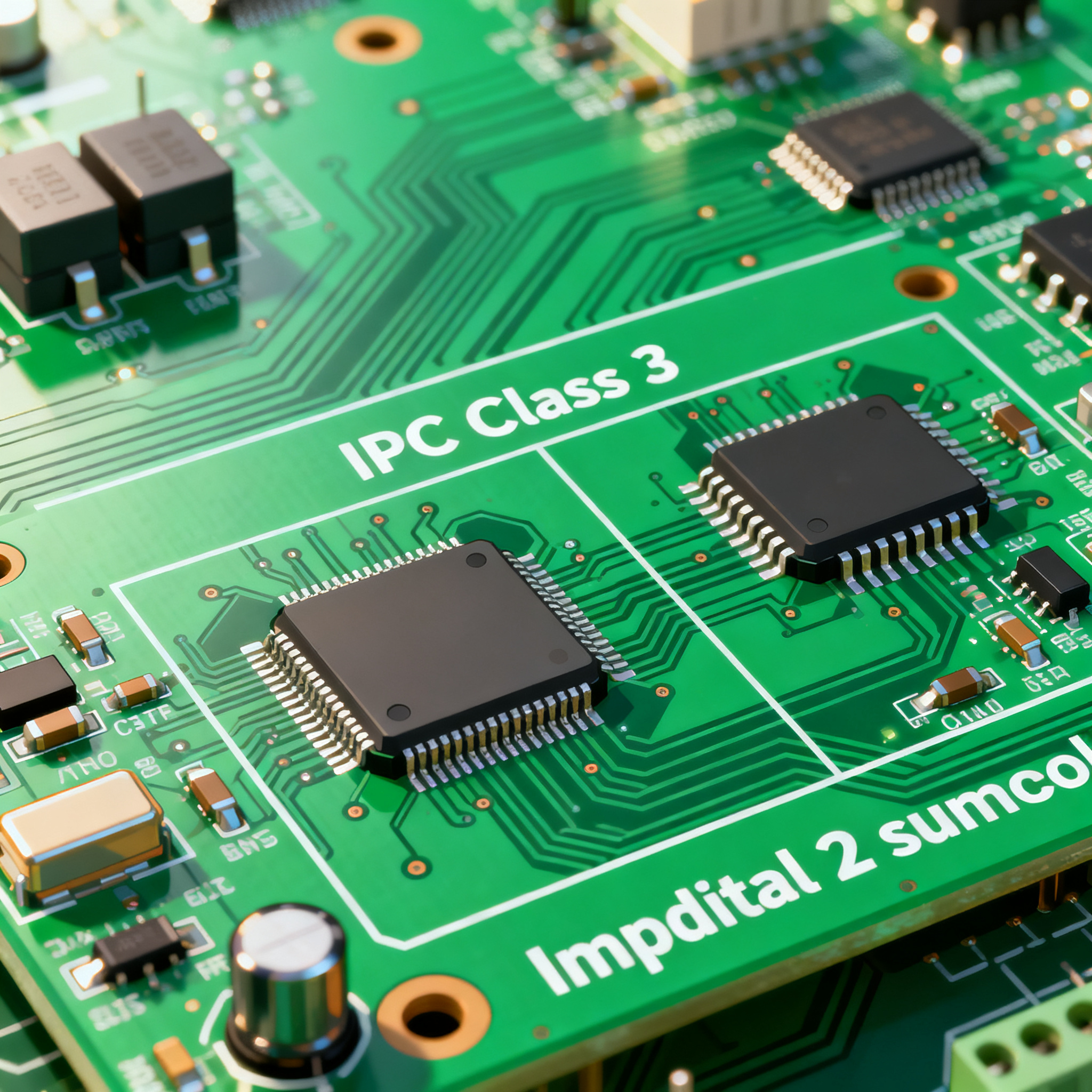
IPC Class 3 vs. Class 2 Medical PCB Assembly: A Selection Guide for Implantable and External Device Reliability
When ‘Class 3’ Isn’t Enough: The Implantable Reliability Imperative Medical electronics don’t get second chances. A failed patient monitor might trigger an alarm; a failed implantable defibrillator ca...
When ‘Class 3’ Isn’t Enough: The Implantable Reliability Imperative
Medical electronics don’t get second chances. A failed patient monitor might trigger an alarm; a failed implantable defibrillator can end a life. That stark difference is why IPC-A-610 Class 3 has become the de facto floor for medical PCB assembly, not a ceiling. Yet many design teams still treat the jump from Class 2 to Class 3 as a simple box to check on a drawing note, without understanding the acceptance criteria that actually separate a commercial-grade board from one that can survive a decade inside the human body.
Industry consensus is clear: medical device PCBAs are specified to Class 3 for implantable devices, life-support systems, and Class II or III medical equipment under both FDA and EU MDR frameworks. The reason is straightforward — Class 3 covers products where failure is not acceptable, and the workmanship requirements reflect that with the tightest annular ring allowances, zero‑void solder joints on critical terminations, and 100% inspection coverage. Even a single latent defect that escapes into a pacemaker or neurostimulator can trigger a field return that costs far more than the assembly premium.
Now the conversation is moving further. The industry is actively discussing a proposed Class 3A category to address ultra‑high‑reliability applications like implantable medical devices and autonomous vehicles. This class would impose even stricter defect limits and require objective evidence of process capability — essentially demanding that manufacturers prove their line can hit Class 3 yields before a single production board is built. While not yet a published standard, the discussion signals that for next‑generation implants, Class 3 may soon be viewed as the minimum, not the gold standard.
For engineers and buyers navigating medical PCB assembly today, the practical question is no longer “should I specify Class 3?” but “when is Class 2 acceptable, and what does Class 3 really change in my design, cost, and supply chain?” The following sections unpack those decisions with real acceptance criteria, cost data, and regulatory mapping.
Decoding IPC-A-610 Acceptance: Where Class 2 Ends and Medical Reliability Begins
IPC-A-610 defines three quality classes, but the gap between Class 2 and Class 3 is where medical reliability is won or lost. Class 2 is intended for dedicated‑service industrial products where extended life is desired but occasional downtime is tolerable. Class 3 demands continuous performance with zero downtime — the environment of an implantable pulse generator or an infusion pump controller that cannot reboot. The difference shows up in measurable workmanship parameters that directly affect field life.
The table below captures the key acceptance criteria that separate the two classes for medical PCB assemblies, based on IPC-A-610H and widely cited by EMS providers specializing in life‑science electronics (PCBCart), (SFX PCB), and (Wevolver).
| Parameter | IPC Class 2 Requirement | IPC Class 3 Requirement | Medical Reliability Impact |
|---|---|---|---|
| Minimum annular ring (external) | 0.050 mm (or 0.040 mm with reduced allowance) | 0.050 mm (no reduction permitted) | Prevents barrel cracking under thermal cycling in implant environments |
| Solder joint voiding (BGA/CSP) | ≤25% void area per joint | ≤15% void area per joint, often 10% for critical joints | Voids accelerate creep fatigue; Class 3 limits extend implant life beyond 10 years |
| Plating thickness (through‑hole) | 20 µm average, 18 µm minimum | 25 µm average, 20 µm minimum | Thicker copper resists stress fractures during repeated sterilization cycles |
| Conductor spacing (minimum) | 0.1 mm (4 mil) typical | 0.1 mm but with tighter etch control; no nicks >20% of width | Reduces dendritic growth risk in high‑humidity body‑worn devices |
| Cleanliness (ionic contamination) | ≤1.56 µg/cm² NaCl equivalent | ≤1.56 µg/cm² but often verified per J‑STD‑001 for medical | Residue‑induced leakage can corrupt low‑level biopotential signals |
| Inspection coverage | Statistical sampling (AOI + visual) | 100% AOI, 100% X‑ray on all BGA/QFN joints | Eliminates latent opens that only appear after implant insertion |
| Traceability | Lot‑level traceability | Full component‑level traceability with date codes | Required for FDA recalls and EU MDR post‑market surveillance |
What the table doesn’t show is the compounding effect of these individual criteria. A 15% void limit might seem academic until you realize that a 0.5 mm pitch BGA on a rigid‑flex implantable PCB sees daily temperature swings from 37°C body heat to cold sterilization cycles. The combination of tighter annular ring, thicker plating, and full X‑ray inspection is what keeps that joint intact after 100,000 thermal cycles. Very small conductor geometries require advanced equipment and tight process control to meet IPC Class III requirements without yield loss, which is why many fabricators reserve dedicated Class 3 lines for medical work.
Tip: When reviewing a supplier’s Class 3 capability, ask for their actual process capability indices (Cpk) on annular ring and plating thickness, not just a certificate. A Cpk below 1.33 on these parameters means they’re barely meeting the spec, and your implantable board may see fallout during lot acceptance testing.
The 15–35% Cost Premium and 2–5 Day Lead Time Penalty: Is Class 3 Always Worth It?
Upgrading a medical PCB assembly from Class 2 to Class 3 isn’t a paperwork exercise — it adds real cost and schedule. According to Queen EMS’s detailed cost comparison, moving to Class 3 adds 15%–35% to your total assembly cost and 2–5 days to your lead time. The drivers are the mandatory 100% inspection, X‑ray on every BGA joint, and the additional process controls that slow down production. For a prototype run of 10 implantable rigid‑flex boards, that might mean an extra $3,000 and a week of schedule; for a production lot of 1,000 external diagnostic devices, it could mean $50,000 and a month of delays.
The decision tree isn’t uniform across all medical devices. The table below breaks down when the Class 3 premium is non‑negotiable and when Class 2 may be a defensible engineering choice.
| Comparison Metric | Class 2 Medical PCB Assembly | Class 3 Medical PCB Assembly | Selection Criteria & Failure Boundary |
|---|---|---|---|
| Typical cost adder vs. Class 2 | Baseline | +15% to +35% | Acceptable for implantables; may be over‑spec for a disposable temperature probe |
| Lead time impact (prototype) | Standard 5–7 days | +2–5 days (7–12 days total) | Plan for Class 3 in development schedule; some EMS providers offer expedited Class 3 lines |
| Inspection method | AOI sampling, visual | 100% AOI, 100% X‑ray on BGAs, often flying probe | Required when a single latent BGA open can cause device failure |
| Acceptable defect rate (AQL) | 0.65% or 0.40% per lot | Zero defects on critical characteristics | Class 3 effectively demands C=0 sampling plans; any defect found triggers 100% reinspection |
| Typical medical applications | External patient monitors, diagnostic ultrasound, non‑invasive sensors | Implantable pacemakers, neurostimulators, infusion pumps, surgical robots | If the device sustains life or its failure could cause injury, Class 3 is mandatory |
| Design rule flexibility | Standard annular rings, no teardrops required | Larger annular rings, teardrops on vias, restricted via‑in‑pad | Implantable rigid‑flex designs must accommodate these rules early to avoid respins |
Strategic component selection balances durability with cost versus higher IPC classes. For a wearable ECG patch that is replaced weekly, Class 2 with selective gold flash on contacts may be perfectly adequate. But for a cochlear implant processor that must survive 15 years of continuous use, the 15–35% premium is cheap insurance against a recall that could cost millions and damage a brand’s reputation. Class 3 is required for medical, aerospace, and defence applications precisely because the cost of failure dwarfs the assembly premium.
One nuance often missed: the cost adder isn’t linear. If your design already uses advanced laminates like polyimide for a rigid‑flex implant, the incremental cost of Class 3 inspection may be modest because the fabrication process is already tightly controlled. The real pain comes when you try to upgrade a legacy Class 2 design to Class 3 without adjusting pad geometries and layer stackup — yield loss can push the effective cost premium well above 35%.
Regulatory Alignment: Matching IPC Class to FDA Device Classification and EU MDR
IPC class selection doesn’t happen in a regulatory vacuum. FDA and EU MDR risk classifications directly inform the expected reliability level, and auditors will ask why you chose Class 2 for a device that could cause harm if it fails. The mapping below is drawn from Proto Express’s medical device regulations overview, Calpak’s Class 3 assembly guide, and the earlier cited Escatec and Wevolver sources.
| Device Classification | FDA Class / EU MDR Risk | Recommended IPC Class | Additional Standards & Testing |
|---|---|---|---|
| Non‑invasive, low‑risk (e.g., digital thermometer, examination light) | FDA Class I / MDR Class I | Class 2 acceptable; Class 3 for brand protection | ISO 13485 QMS, basic EMC testing |
| External diagnostic, moderate risk (e.g., patient monitor, ultrasound, wearable ECG) | FDA Class II / MDR Class IIa or IIb | Class 2 often sufficient; Class 3 for life‑support functions | ISO 14971 risk management, IEC 60601‑1, traceability per 21 CFR 820 |
| Implantable, life‑sustaining (e.g., pacemaker, ICD, neurostimulator, implantable sensor) | FDA Class III / MDR Class III | Class 3 mandatory; Class 3A discussions apply | MIL‑STD‑883 for die‑level reliability, HALT/HASS, full component traceability, NADCAP or ISO 13485 certified assembly |
| Surgical tools, high‑risk external (e.g., robotic surgery controller, infusion pump) | FDA Class II or III / MDR Class IIb or III | Class 3 strongly recommended | 100% X‑ray, cleanliness per J‑STD‑001, often ITAR‑controlled data handling if defense‑adjacent |
The regulatory link is not just about ticking a box. Under EU MDR, manufacturers must demonstrate a proactive risk management process per ISO 14971. If your risk analysis identifies a hazardous situation where PCB failure could lead to patient harm, and you haven’t specified Class 3 with full traceability, a notified body may issue a non‑conformity. Calpak notes that Class III medical devices typically require Class 3 with additional requirements per MIL‑STD-883 or customer specifications, and that ITAR‑controlled technical data handling may apply if the device has defense crossover. This is why many medical device startups engage an assembly partner with both ISO 13485 and defense‑grade Class 3 lines early in design — it simplifies the audit trail later.
Traceability deserves special emphasis. FDA’s Quality System Regulation (21 CFR Part 820) and EU MDR both require that you can trace every component on a life‑sustaining device back to its lot and date code. Class 3 assembly inherently supports this with full component‑level traceability, while Class 2 often stops at lot‑level. If you ever need to execute a recall on an implantable device, the difference between lot‑level and component‑level traceability can mean recalling 100 units versus 10,000 — a financial chasm.
Medical PCB Assembly Class Selection: Questions Engineers and Buyers Actually Ask
In our work with medical device teams at NovaPCBA, certain questions surface repeatedly — from senior engineers finalizing a rigid‑flex stackup to procurement managers negotiating lead times. Here are the answers that go beyond the textbook definitions.
Q: Can I specify IPC Class 2 for a wearable medical device that isn't life-sustaining?
Yes, for many FDA Class I devices and some Class II external monitors, Class 2 is technically acceptable. A disposable temperature patch or a fitness‑grade heart rate monitor rarely demands the zero‑defect rigor of Class 3. However, you must document the decision through a risk analysis per ISO 14971. If the wearable provides diagnostic data that influences clinical decisions, a notified body may still expect Class 3. Some manufacturers choose Class 3 anyway for brand protection — a field failure in a consumer‑facing wearable can trigger social media backlash that outweighs the assembly cost savings.
Q: What design rule changes are required when moving from Class 2 to Class 3 for an implantable rigid-flex PCB?
You’ll need larger annular rings (0.050 mm minimum with no reduction), teardrops on vias to prevent stress fractures during flexing, and careful restriction of via‑in‑pad structures. Tighter conductor spacing allowances may force you to increase trace widths or adjust layer count. Very small conductor geometries often require advanced laminates like polyimide or ceramic to maintain yield at Class 3. Start with your fabricator’s design for manufacturability (DFM) feedback early — retrofitting Class 3 rules onto a completed Class 2 layout can trigger a complete respin.
Q: How does the proposed IPC Class 3A differ from Class 3, and should I design for it now?
Class 3A, as discussed in the industry, would impose even stricter defect limits — for example, zero voiding on BGA joints and tighter Cpk requirements on every process step — and would require objective evidence of process capability before production. While not yet a standard, forward‑thinking teams are already discussing it with their assembly partners. If you’re designing a next‑generation implantable neurostimulator with a 20‑year service life, aligning your DFM with anticipated Class 3A criteria can future‑proof the design and reduce requalification costs later.
Q: What should I ask a PCB assembly supplier to verify their Class 3 medical capability?
Request evidence of NADCAP or ISO 13485 certification specific to medical electronics, not just a generic ISO 9001. Ask for audit reports showing 100% AOI and X‑ray coverage, process control data for plating thickness (Cpk ≥ 1.33), and ionic cleanliness test results per J‑STD‑001. Compare their capabilities against benchmarks like Calpak’s defense‑grade Class 3 lines, which often include additional MIL‑STD‑883 testing. A capable supplier should be able to provide a process capability study for your specific board design, not just a generic certificate.
Q: Does specifying Class 3 add significant lead time for prototype runs?
Yes, typically 2–5 days extra due to 100% inspection and mandatory X‑ray, as Queen EMS’s data shows. However, some EMS providers have streamlined Class 3 prototype lines that can turn boards in 7–8 days if the design is mature and materials are on hand. Plan for this early in your development schedule — don’t expect a Class 3 prototype in the same 5‑day window as a Class 2 build.
Q: Are there material limitations when meeting Class 3 for high-density implantable PCBs?
Absolutely. When conductor widths drop below 75 µm (3 mil), standard FR‑4 may not provide the dimensional stability needed to hold Class 3 annular ring tolerances. Polyimide, Teflon, ceramic, or other advanced laminates become necessary, and yield can drop sharply without tight process control. Work closely with your fabricator to select materials that balance electrical performance, biocompatibility (if applicable), and manufacturability. Often a hybrid stackup — polyimide flex layers with rigid FR‑4 stiffeners — offers the best compromise for implantable rigid‑flex designs.
References & Further Reading
- IPC-A-610 Class 1, 2, & 3 explained: Choosing the right standard for your PCBA – Escatec
- IPC-A-610: Acceptability of Electronic Assemblies – Wevolver
- Guide to IPC Standards and Certifications for PCB Production – SFX PCB
- IPC-A-610 Class 3 Standards for High-Reliability Life Sciences Electronics Assemblies – PCBCart
- Stop Overpaying: IPC Class 2 vs Class 3 PCB Cost Comparison – Queen EMS
- IPC Class Definition | Class 2 vs Class 3: Different PCB Design Rules – PCBasic
- Medical Device PCBs – IPC Class II and IPC Class III Specifications – Epec
- Medical PCB: Complete Guide to Design, Manufacturing & Assembly – PCBSync
- Medical Device Regulations for PCB Assembly – Proto Express
- IPC Class 3 PCB Assembly Guide — Requirements & Standards – Calpak USA
At NovaPCBA, we bring over a decade of experience in medical PCB assembly, from Class 2 external diagnostic boards to full Class 3 implantable rigid‑flex systems. Our ISO 13485‑certified lines combine 100% AOI, X‑ray, and ionic cleanliness verification to meet the most demanding life‑science requirements. Explore our medical PCB assembly capabilities or contact our engineering team to discuss your next implantable device project.