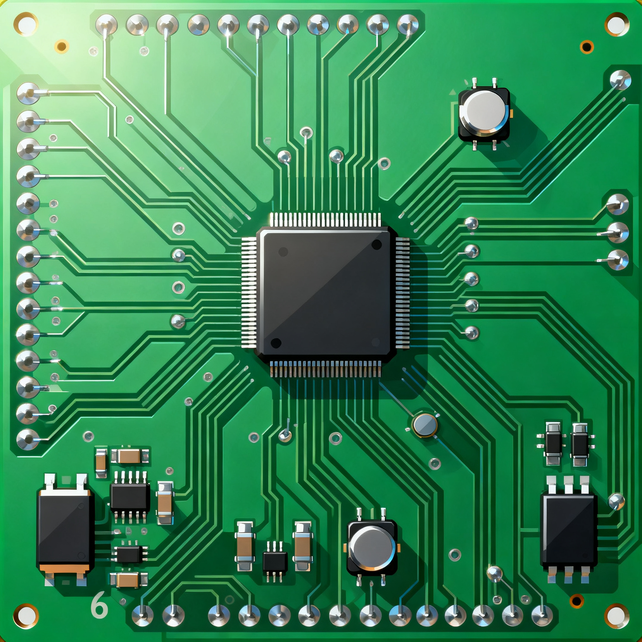
How to Design and Assemble a 6-Layer High-Voltage PCB for New Energy Vehicle Motor Controllers: A Step-by-Step Guide
Why 800V Platforms Are Forcing a 6-Layer Rethink in Motor Controller PCBs The move from 400V to 800V traction architectures in new energy vehicles isn’t just a battery-pack upgrade — it’s a fundamenta...
Why 800V Platforms Are Forcing a 6-Layer Rethink in Motor Controller PCBs
The move from 400V to 800V traction architectures in new energy vehicles isn’t just a battery-pack upgrade — it’s a fundamental redesign of the motor controller’s power stage. When you double the bus voltage, you halve the current for the same power output, but you also double the electric field stress across every insulating surface inside the PCB. That stress exposes weaknesses that 4‑layer boards, even with 2oz copper, can’t reliably handle over a 15‑year vehicle lifetime.
Today’s 800V platforms routinely push motor controllers past 200 A peak phase current, with DC‑link voltages reaching 900 V during regenerative braking or fast charging. Aivon’s analysis of 800V systems highlights that the shift from 400V to 800V brings significant advantages in charging speed and power density, but it also demands a complete re‑evaluation of insulation coordination. A 4‑layer board that worked at 400 V may see creepage distances shrink below safe margins when the working voltage doubles. The result is a higher risk of conductive anodic filament (CAF) growth, surface tracking, and eventual dielectric breakdown — failures that are catastrophic in a motor inverter.
Thermal management adds another dimension. At 800 V, the same power output means lower current, but switching losses in SiC MOSFETs and IGBTs remain substantial. The PCB must spread heat away from power devices while maintaining isolation. A 6‑layer stackup gives you dedicated inner planes for heat spreading and high‑voltage shielding that a 4‑layer board simply cannot provide. As the TopfastPCBA power electronics design guide explains, copper thickness, thermal management, and EMI control are interlinked in EV designs; a robust 6‑layer PCB becomes the baseline when currents exceed 40 A and voltages climb above 600 V.
Engineers who try to squeeze an 800 V motor drive onto a 4‑layer board often run into clearance creep: the space between high‑voltage traces and low‑voltage control signals shrinks until the layout violates IPC‑2221 pollution degree 2 requirements. The PCBSync 6‑layer PCB overview notes that the 6‑layer board represents a practical step up from 4‑layer designs for those that genuinely need additional routing capacity, improved signal integrity, or better power distribution — and motor controllers fall squarely into that category. The extra two layers let you segregate the high‑voltage traction domain, the gate‑drive stage, and the low‑voltage control circuitry, each with its own reference plane. This segregation is not a luxury; it’s the difference between a design that passes hipot testing on the first prototype and one that arcs over during thermal cycling.
Inside a 6-Layer HV PCB: Stackup, Copper, and Clearance for Motor Control
A well‑designed 6‑layer motor controller PCB uses the stackup to create three distinct electrical domains. Typically, layers 1 and 6 carry high‑current power traces and component pads; layers 2 and 5 act as ground and power‑plane returns; and layers 3 and 4 route gate‑drive signals and low‑voltage control logic. This arrangement minimizes crosstalk between the noisy switch‑node and sensitive microcontroller inputs, while keeping the high‑voltage planes buried away from the outer surfaces where contamination could initiate tracking.
The Aivon 6‑layer stackup guide for power electronics emphasizes that copper weight, prepreg thickness, and isolation techniques must be selected together to meet both thermal and dielectric requirements. For an 800 V motor controller, a common starting point is a symmetrical stackup with 2oz outer layers and 2oz or 1oz inner planes, using high‑Tg FR4 (≥170 °C) and a core thickness chosen to achieve at least 0.4 mm of solid insulation between high‑voltage and low‑voltage domains. The table below compares four stackup configurations that are regularly specified for EV motor drives.
| Stackup Variant | Layer Copper Weights (L1–L6) | Core/Prepreg Thickness (Typical) | Creepage Achieved (Outer Layers) | Best Suited For |
|---|---|---|---|---|
| 2oz/1oz/1oz/1oz/1oz/2oz | 70 µm outer, 35 µm inner | 0.2 mm core, 0.15 mm prepreg | ~3.2 mm (pollution degree 2) | 400 V–600 V drives, moderate current |
| 2oz/2oz/1oz/1oz/2oz/2oz | 70 µm outer, 70 µm L2/L5, 35 µm L3/L4 | 0.25 mm core, 0.18 mm prepreg | ~4.0 mm | 800 V drives up to 150 A phase current |
| 3oz/2oz/1oz/1oz/2oz/3oz | 105 µm outer, 70 µm L2/L5 | 0.3 mm core, 0.2 mm prepreg | ~4.5 mm | 800 V drives >150 A, heavy thermal cycling |
| 2oz/2oz/2oz/2oz/2oz/2oz (all 2oz) | 70 µm all layers | 0.2 mm core, 0.15 mm prepreg | ~3.5 mm | Cost‑sensitive 400 V designs; not recommended for 800 V without conformal coating |
In the 2oz/2oz/1oz/1oz/2oz/2oz stackup, the inner 1oz layers carry gate signals and low‑voltage logic, while the 2oz inner planes (L2 and L5) serve as shields and return paths. The outer 2oz layers handle the high‑current power loops. The 3oz variant pushes current capacity further but demands careful attention to solderability and via plating — topics we’ll address in the manufacturability section. The PCBSync 6‑layer analysis notes that controlled impedance, blind/buried vias, and special materials can extend lead times, so sticking with a symmetrical, all‑through‑hole stackup keeps prototyping cycles short.
Creepage and clearance values in the table assume pollution degree 2 and functional insulation per IPC‑2221. For reinforced insulation or pollution degree 3 (common in under‑hood environments), you may need to increase distances by 50% or apply conformal coating. The stackup alone cannot guarantee safety; layout discipline is equally critical. High‑voltage nodes must be kept away from board edges, and any inner‑layer splits must maintain the same clearance as outer layers to prevent internal tracking.
Stackup Showdown: 2oz vs. 3oz Copper and Standard FR4 vs. High-Tg for Motor Controllers
Choosing between 2oz and 3oz copper, and between standard FR4 and high‑Tg laminates, is one of the most consequential decisions in a motor controller PCB design. Each option influences current handling, thermal performance, manufacturability, and cost in ways that ripple through the entire project. The table below draws on insights from four industry references — Aivon’s 800V platform article, the TopfastPCBA EV power‑electronics guide, Aivon’s custom motor‑drive PCB guide, and the PCBSync 6‑layer PCB overview — to present a balanced comparison.
| Comparison Metric | 4‑Layer, 2oz, Standard FR4 | 6‑Layer, 2oz, High‑Tg FR4 | 6‑Layer, 3oz, High‑Tg FR4 | Selection Criteria & Failure Boundary |
|---|---|---|---|---|
| Typical Phase Current Capability | Up to 40 A (with thermal vias) | 80–150 A | 150–250 A | Exceeding 40 A on 4‑layer risks trace delamination and excessive I²R heating. |
| Voltage Rating (Functional Insulation) | 400 V nominal | 800 V nominal | 800 V nominal | At 800 V, 4‑layer boards struggle to meet 3.2 mm creepage without sacrificing routing density. |
| Thermal Conductivity (Through‑Plane) | ~0.3 W/m·K | ~0.4 W/m·K | ~0.5 W/m·K | Higher copper content improves heat spreading; 3oz reduces hot‑spot ΔT by 15–20%. |
| Glass Transition Temperature (Tg) | 130–140 °C | 170–180 °C | 170–180 °C | Standard FR4 softens above 130 °C; high‑Tg prevents delamination during lead‑free reflow and continuous operation at 120 °C. |
| Manufacturability | Standard process, high yield | Moderate; requires controlled impedance etching | Challenging: heavy copper etching, via plating, and soldering demand extended process windows | 3oz designs need stepped stencils, extended preheat, and often vacuum reflow to avoid voids. |
| Relative Cost (PCB Fabrication) | 1.0× (baseline) | 1.3–1.5× | 1.8–2.2× | Cost delta is justified by reduced field failures and warranty claims in 800 V systems. |
| EMI Control | Poor — no dedicated shield planes | Good — dedicated ground/power planes reduce loop area | Excellent — thicker planes lower impedance, further suppressing ringing | For SiC inverters with dv/dt >50 V/ns, 6‑layer with 2oz planes is the minimum for radiated emissions compliance. |
The 4‑layer, 2oz option remains viable for auxiliary motor drives or low‑power 400 V systems, but as the Aivon motor‑drive guide points out, a 4‑layer board with 2oz copper can safely manage 40 A with less risk of overheating than a 2‑layer design — yet it forces tighter clearance compromises. When you step up to 800 V, the 6‑layer, 2oz, high‑Tg configuration becomes the sweet spot for most traction inverters. It balances cost and performance while providing the necessary isolation headroom. The 3oz variant is reserved for the highest power densities, where every degree of temperature rise matters and the BOM cost can absorb the fabrication premium.
One often‑overlooked factor is the coefficient of thermal expansion (CTE) mismatch. High‑Tg FR4 has a lower CTE in the Z‑axis, which reduces the risk of plated‑through‑hole barrel cracking during thermal cycling. For motor controllers that see junction temperatures swing from −40 °C to +150 °C daily, this reliability gain alone can justify the material upgrade.
Designing and Assembling for Manufacturability: Tips to Avoid Voltage Breakdown and Thermal Runaway
Even the best stackup can fail if layout and assembly practices don’t account for the realities of high‑voltage, high‑current manufacturing. The following guidelines, grounded in Megabyte Circuit’s EV PCB standards guide and the PCBSync automotive PCB assembly guide, will help you avoid the most common pitfalls.
- Maintain creepage and clearance from the start. For an 800 V working voltage, outer‑layer creepage should be at least 3.2 mm (pollution degree 2) per IPC‑2221. If the controller operates in a pollution degree 3 environment (e.g., near the motor, exposed to dust and moisture), increase that to 5 mm or apply a conformal coating rated for the voltage. Never rely on solder mask alone as an insulator; it is porous and not rated for high‑voltage isolation.
- Stitch thermal vias under every power device. Use an array of 0.3 mm diameter vias with 0.8 mm pitch directly beneath MOSFET or IGBT drain pads. Connect them to inner copper planes to spread heat laterally. For 3oz copper, specify via plugging with thermally conductive epoxy to prevent solder wicking during assembly.
- Balance copper distribution on each layer. Asymmetric copper can cause board warpage during reflow, especially on thick, heavy‑copper boards. The Aivon 6‑layer stackup guide recommends keeping the copper fill percentage within 10% across all layers. Add copper thieving on sparse layers to maintain symmetry.
- Use a stepped stencil for heavy‑copper SMT assembly. The PCBSync automotive assembly guide highlights that heavy copper creates large thermal mass, causing tombstoning and poor solder joint formation. A stepped stencil — thicker over power pads, thinner over small passives — ensures adequate paste volume without bridging. Pair this with a reflow profile that includes an extended soak at 150–170 °C for 90–120 seconds and a peak temperature of 240–245 °C.
- Specify IPC‑6012DA Class 3 for plating integrity. The Megabyte Circuit EV standards guide notes that automotive PCBs must meet stricter criteria for copper plating thickness and hole wall integrity. For motor controllers, Class 3 ensures that plated through‑holes can withstand the thermal and mechanical stresses of 1,000+ thermal cycles without barrel cracking.
- Control EMI at the source. Keep the high‑di/dt gate‑drive loop as small as possible. Route the gate signal and its return path as a tightly coupled differential pair on an inner layer, sandwiched between ground planes. The TopfastPCBA power electronics guide stresses that proper layout of the DC‑link bus and snubber circuits is essential to suppress ringing that can couple into low‑voltage circuits.
For thermal management, the table below summarizes the minimum design rules that have proven effective in production motor controllers. These values assume natural convection with an external heatsink attached to the PCB or power module baseplate.
| Design Parameter | Recommended Value | Notes |
|---|---|---|
| Thermal via diameter / pitch | 0.3 mm / 0.8 mm | Smaller vias reduce voiding risk; fill with epoxy for 3oz copper. |
| Copper plane thickness under device | ≥70 µm (2oz) on layer directly beneath | 3oz preferred for >100 W dissipation per device. |
| Minimum prepreg thickness between HV and LV planes | 0.2 mm (two sheets of 1080 prepreg) | Ensures >1.5 kV dielectric withstand. |
| Conformal coating type | Silicone or acrylic, 50–100 µm thickness | Apply after assembly; mask connectors and test points. |
| Reflow peak temperature (lead‑free) | 240–245 °C | Extended time above liquidus (60–90 s) for heavy copper. |
| Annular ring for through‑hole vias | ≥0.3 mm | Per IPC‑6012DA Class 3; larger rings improve reliability under thermal stress. |
When you follow these rules, the 6‑layer board becomes a robust platform that survives the rigors of EV operation. At NovaPCBA, we’ve seen that early collaboration between design and assembly teams is the single biggest factor in first‑pass success. Specifying the stackup, surface finish, and assembly profile together — rather than treating them as sequential steps — eliminates the surprises that delay production ramp‑up.
Motor Controller PCB FAQs for Engineers and Sourcing Buyers
Q: What is the minimum creepage distance for 800V motor controllers on a 6-layer PCB?
For functional insulation at 800 V working voltage, IPC‑2221 calls for roughly 3.2 mm creepage on outer layers with pollution degree 2. If the controller is exposed to condensation or conductive dust (pollution degree 3), that requirement jumps to 5 mm or more. Always consult IEC 60664‑1 for the end‑product isolation coordination, as the required creepage may increase for reinforced insulation or altitudes above 2,000 m. In practice, many Tier 1 suppliers design for 4–5 mm on outer layers and apply conformal coating to gain an extra safety margin.
Q: How do I balance cost and performance when choosing between 4-layer and 6-layer boards?
A 4‑layer board with 2oz copper can handle 40 A, as noted in Aivon’s motor‑drive guide, but it forces tighter clearance compromises at 800 V. A 6‑layer stackup with dedicated high‑voltage planes reduces the risk of breakdown and EMI, which lowers long‑term warranty costs. The fabrication cost delta is typically 20–30% more for the 6‑layer, but that premium is quickly offset by fewer field failures, simpler EMC qualification, and the ability to use standard FR4 instead of exotic high‑voltage laminates. For production volumes above 10,000 units per year, the 6‑layer approach is almost always the more economical choice over the product lifecycle.
Q: What PCB surface finish is best for high-voltage motor controllers?
ENIG (electroless nickel immersion gold) is common for its flatness and corrosion resistance, but the nickel layer can migrate under high electric fields, potentially forming conductive filaments. For high‑voltage tracks, OSP (organic solderability preservative) or immersion silver may be preferred because they avoid nickel entirely. Heavy‑copper boards often use lead‑free HASL, but coplanarity must be tightly controlled for SMT assembly — a challenge with 3oz copper. Many automotive designs now use ENEPIG (electroless nickel electroless palladium immersion gold) to combine wire‑bonding compatibility with high‑voltage reliability, though at a higher cost.
Q: How do I ensure reliable SMT assembly with heavy copper layers?
Heavy copper (3oz+) acts as a large heat sink, causing tombstoning, voiding, and poor solder joint formation if the reflow profile isn’t adapted. Use a profile with an extended soak time at 150–170 °C for 90–120 seconds, preheat the board to 100–120 °C before reflow, and consider a stepped stencil — 0.15 mm for small passives and 0.20 mm for power pads. The PCBSync automotive assembly guide emphasizes that IPC‑6012DA Class 3 requirements for hole fill and plating thickness must be met, which often means specifying a minimum copper plating thickness of 25 µm in vias. Vacuum reflow can further reduce voiding in large thermal pads.
Q: What thermal management techniques prevent delamination in 6-layer PCBs?
Delamination occurs when the Z‑axis expansion of FR4 exceeds the bond strength of the resin. To prevent it, use thermal vias under every power semiconductor, specify high‑Tg FR4 (≥170 °C) or polyimide for extreme environments, and balance copper distribution on each layer to avoid asymmetric stress. For motor drives dissipating more than 100 W, add an external heatsink and consider using an insulated metal substrate (IMS) for the power stage, with the control logic on a separate 6‑layer FR4 board. Avoid excessive adhesive thickness in prepreg layers; two sheets of 1080 prepreg are typically sufficient for a 0.2 mm isolation barrier.
Q: When should I specify blind/buried vias versus through-hole vias for HV stacks?
Blind vias are useful when routing density forces connections between surface and inner layers without breaking high‑voltage isolation — for example, connecting a gate‑drive signal from layer 1 to layer 3 without penetrating the high‑voltage plane on layer 2. Buried vias free up surface real estate but add significant cost and lead time, as noted in the PCBSync 6‑layer PCB analysis. For most motor controllers, through‑hole vias with an annular ring ≥0.3 mm and proper anti‑pad clearance are sufficient and more reliable. Reserve blind/buried vias for designs where space constraints are extreme, such as integrated drive modules with the controller mounted directly on the motor housing.
References & Further Reading
- High-Voltage PCB Design for Electric Vehicles: 800V Platforms, Battery Management, and Power Distribution Systems — Aivon
- Power Electronics PCB Design for EV: High Current, Thermal Management & Reliability — TopfastPCBA
- Designing a Custom Electric Motor Drive PCB: A Comprehensive Guide — Aivon
- 6 Layer PCB Explained: Stackup Configurations, Applications & Cost — PCBSync
- 6-Layer PCB Stackup for Power Electronics: Design for High Current and Voltage — Aivon
- Designing PCBs for Electric Vehicles: Standards & Expert Guide — Megabyte Circuit
- Automotive PCB: Design, SMT Assembly & Quality Standards Explained — PCBSync
- Power Electronics PCB Design for EV: High Current, Thermal Management & Reliability — TopfastPCBA
Designing a 6‑layer high‑voltage PCB for an EV motor controller is a multidisciplinary challenge that rewards careful stackup planning, material selection, and close collaboration with your assembly partner. At NovaPCBA, we specialize in manufacturing and assembling thick‑copper, high‑reliability PCBs for automotive traction inverters, bringing together the process control and certifications needed to turn your design into a production‑ready power stage. When you’re ready to move from prototype to volume, our team can help you validate your stackup, optimize your assembly profile, and deliver boards that meet IPC‑6012DA Class 3 requirements — without the lead‑time surprises that plague complex multilayer projects.