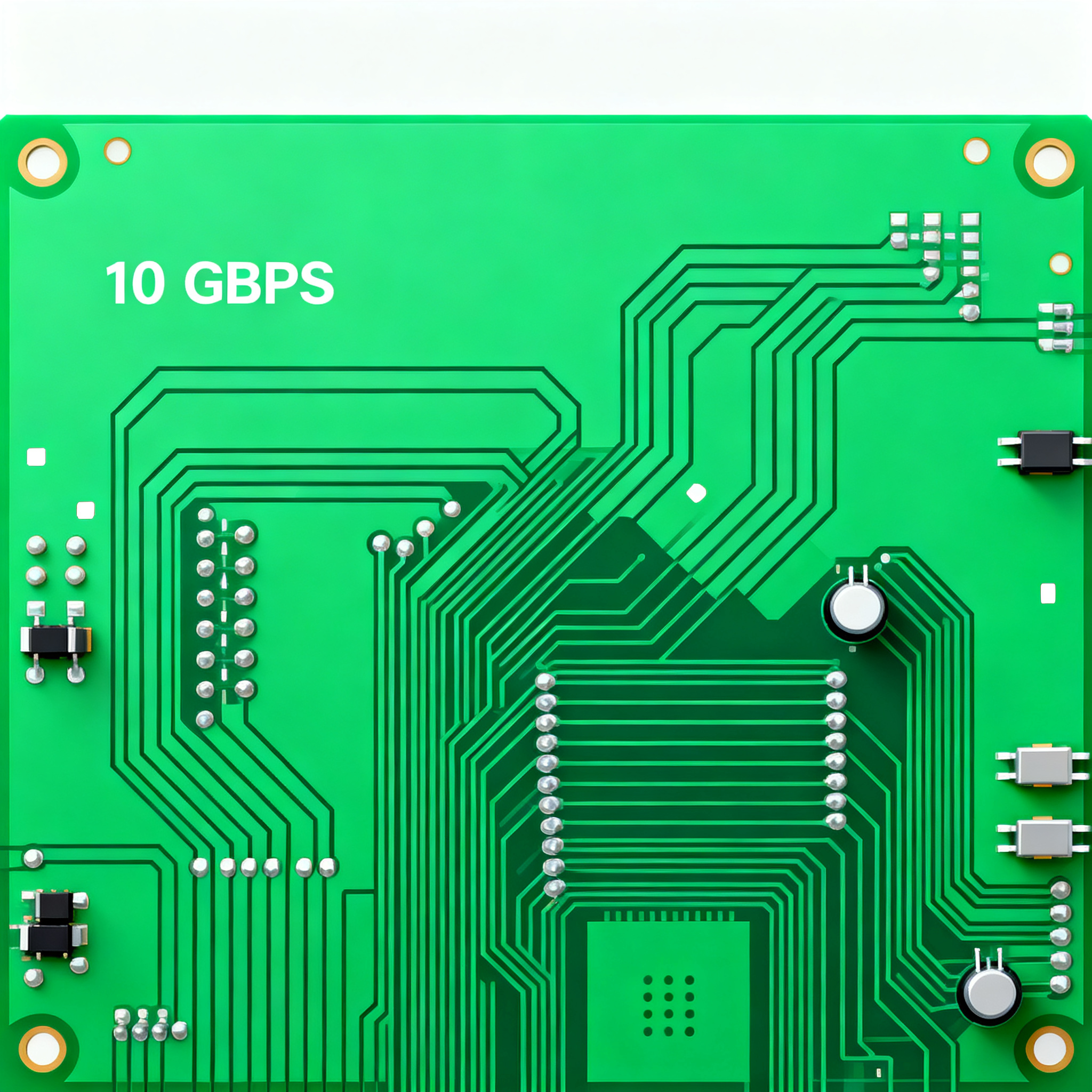
High-Speed PCB Design Field Guide: Routing 10 Gbps Traces, Controlled Impedance, and EMI Mitigation
The 10 Gbps Layout Trap: Why Post-Layout Validation Catches What Your Design Rules Miss You’ve followed every constraint manager rule, length-matched every differential pair, and satisfied the DRC. Ye...
The 10 Gbps Layout Trap: Why Post-Layout Validation Catches What Your Design Rules Miss
You’ve followed every constraint manager rule, length-matched every differential pair, and satisfied the DRC. Yet when the first PCIe Gen 4 board comes back from the fab, the eye diagram is closed, and the link won’t train. What happened? At 10 Gbps, a trace is no longer a simple copper connection—it behaves as a distributed RF transmission line, and static layout checks are blind to the impedance discontinuities, stub resonances, and frequency-dependent losses that degrade the signal.
The most common hidden failure is a leftover via stub. A plated through-hole that connects an inner layer leaves a stub extending to the opposite side of the board. At multi-gigabit data rates, that open stub becomes a quarter-wave resonator that reflects energy back toward the source, collapsing the eye. PCBSync’s field-tested rule sets the limit at one‑quarter wavelength: for a 10 Gbps signal, the stub must stay under about 10 mils. A 15-mil stub that passes DRC without comment can push the bit‑error rate into the red.
Static DRCs can’t model the frequency-dependent behavior of a via stub or the interaction of multiple discontinuities along a channel. That’s why experienced teams add a post‑layout signal integrity (SI) validation step. The workflow described by AESTECHNO extracts actual trace geometry from the routed PCB—including corners, via pads, and plane voids—then feeds that structure into a 3D field solver along with the IBIS/AMI models published by silicon vendors. The simulation predicts eye height, jitter, and compliance with the interface bit‑error‑rate mask. For interfaces above 10 to 12 Gbps (PCIe Gen 4, USB4, 25G Ethernet), simulation is not optional. A single violation in a post‑layout simulation flags a stub that must be backdrilled or a differential pair that needs re‑timing before the board is etched.
Key Takeaway: Treat layout as a preliminary step. The real sign-off for a 10 Gbps board lives in the channel simulation results, not in the DRC report.
How a 10 Gbps Trace Turns Into an RF Transmission Line
When rise times drop into the 30 ps range, the physical dimensions of a trace and its return path span a significant fraction of the signal wavelength. Every via becomes an impedance discontinuity that reflects energy back to the driver. A differential pair that isn’t tight enough on intra‑pair skew collapses into common‑mode noise because the two halves arrive at the receiver out of phase. Flux emphasizes that most high‑speed interface specifications permit skew measured in tens of picoseconds—a few mils of length mismatch can eat the entire budget.
To help you internalize the physical constraints, the table below correlates the critical parameters for a typical 10 Gbps link. Keep these numbers in your head when you push the first trace.
| Parameter | Typical Value at 10 Gbps | Unit | Consequence of Violation |
|---|---|---|---|
| Rise time (20‑80%) | ~30 | ps | Higher inter‑symbol interference, eye closure |
| Maximum allowable via stub length | <10 | mils | Resonant open stub causes reflections and eye collapse |
| Via impedance discontinuity | 5–15% deviation from nominal | Ω | Impedance mismatch, reflections, increased jitter |
| Differential intra‑pair skew budget (PCIe Gen 4) | <5 | ps | Common‑mode noise, EMI, link training failures |
| Single‑ended impedance target | 50 | Ω | Connector and component compatibility, controlled reflection |
| Differential impedance (PCIe) | 100 | Ω | Must match PHY termination; deviation opens the eye |
Notice the interdependence: a 5 ps skew budget forces you to match lengths to within a few mils, while a 10-mil stub limit often mandates backdrilling or blind vias. Standardizing on a 50 Ω single‑ended baseline as Sierra Circuits advises keeps connector selection straightforward and simplifies the transition to 100 Ω differential pairs when stacking two 50 Ω traces. Operating a trace at a different impedance is possible, but any deviation must be justified by the PHY vendor’s specification.
When to Move Beyond FR‑4: Laminate Selection and Impedance Targets for Multi‑Gigabit Links
Not every 10 Gbps design demands exotic laminates, but as soon as the data rate climbs past 10 Gbps and the trace length grows beyond a few inches, the loss tangent of standard FR‑4 eats your margin. A high‑performance FR‑4 with tightly controlled dielectric constant (Dk) can serve many sub‑10 Gbps applications, but for PCIe Gen 4, USB4, or 25G Ethernet, the stable Dk and low loss of a material like Rogers RO4350B become decisive according to Flux. The table below quantifies the trade‑offs.
| Comparison Metric | Standard High‑Performance FR‑4 | Rogers RO4350B | Selection Criteria & Failure Boundary |
|---|---|---|---|
| Dielectric Constant (Dk) at 10 GHz | 3.8 – 4.2 (varies with glass/resin ratio) | 3.48 ±0.05 | Dk variation >0.1 causes impedance errors; RO4350B guarantees tight tolerance. |
| Dissipation Factor (Df) at 10 GHz | 0.015 – 0.020 | 0.0037 | Lower Df cuts insertion loss; essential for long PCIe Gen 4 lanes or 25G links. |
| Dk Stability vs. Frequency (500 MHz – 40 GHz) | Gradual drift, greater dispersion | Nearly flat response | Wide‑bandwidth protocols demand flat Dk to avoid phase distortion; FR‑4 may fail high‑end SerDes equalization. |
| Fabrication Impedance Tolerance | ±10% (tighter possible with advanced Dk control) | ±5% (achievable with controlled‑impedance process) | PCIe Gen 4/5 require ±5% or better; a fab like Sierra Circuits offers ±5% even on FR‑4, but the laminate’s inherent Dk spread can still challenge the target. |
| Cost Multiplier vs. Baseline FR‑4 | 1× | 2–4× depending on layer count | Use premium FR‑4 for sub‑10 Gbps short‑reach links; mandate RO4350B for long-haul or when loss budget is near zero. |
Beyond material choice, the exact impedance target is not a generic “100 Ω rule of thumb.” Autodesk’s high‑speed design guide emphasizes that the differential pair mismatch limit comes from the interface specification, not a layout textbook. USB 3.2 requires 90 Ω differential, whereas PCIe wants 100 Ω. If your fabricator cannot hold a ±5% tolerance on those numbers—and prove it with impedance coupons from the same panel—the design is at risk. Before releasing Gerbers, confirm that your fabricator’s controlled‑impedance capability matches the demands of the PHY you selected.
Four Non‑Negotiable Rules for Routing 10 Gbps Traces Over Ground
These four rules have been proven in hundreds of 10+ Gbps designs. They are not suggestions—skipping any one of them will show up in the lab as bit errors, EMI failures, or a dead link.
- Always route high-speed signals adjacent to a solid ground reference plane. Never place two signal layers back-to-back in the stackup, a condition known as broadside coupling. Ultra Librarian warns that route increases crosstalk and creates impedance discontinuities. Instead, sandwich each routing layer between a power or ground plane, and keep the dielectric thin for tight field containment.
- Create generous routing channels and segregate analog from digital. Cadence’s layout guidelines stress allowing routing channels for dense buses and positioning parts to keep analog and digital return currents apart. In a mixed‑signal design, a single 10 Gbps lane wandering through the analog section couples noise onto sensitive nodes and compromises the entire system.
- Eliminate via stubs—backdrill or use blind vias. A through‑hole via that connects an inner layer without backdrilling leaves a stub that becomes a resonant circuit. Sierra Circuits’ routing practices explain that even small stubs degrade eye diagram integrity. Either backdrill all vias on high‑speed nets to a controlled depth or switch to blind vias that stop at the target layer.
- Validate every critical channel with a post‑layout SI solver. Layout‑only checks cannot model frequency-dependent loss, reflections, or crosstalk across a complete daisy chain. AESTECHNO’s methodology extracts the 3D geometry and runs IBIS/AMI simulations to verify that the eye opening at the receiver meets the required mask. This step must be completed before CAD data is released to the fab.
Below is a practical comparison of the via technologies you’ll use to enforce Rule 3. The right choice depends on your layer count, budget, and the density of the BGA escape region.
| Via Method | Stub Length (typical after process) | Cost Impact | Signal Integrity at 10 Gbps | Notes |
|---|---|---|---|---|
| Standard through‑hole (no backdrill) | Full board thickness minus routed depth; often >50 mils | No adder | Poor—stub resonance destroys eye | Acceptable only for legacy <1 Gbps signals |
| Backdrilled via | <10 mils (controlled depth drill) | Moderate adder; requires extra drill file and careful registration | Excellent; eliminates stub resonance | Preferred for high‑count, dense PCBs where blind vias are too expensive |
| Blind via (laser drilled from outer layer) | Zero if via stops at the target layer | Higher; adds sequential lamination steps | Excellent; no stub and lower parasitic capacitance | Ideal for fine‑pitch BGA escape; often paired with microvia‑in‑pad |
The via strategy must be decided during stackup planning, not as an afterthought. Blind vias simplify routing but raise fabrication cost; backdrilling offers a cost‑effective compromise when the via count is manageable.
Senior Engineer’s Sign‑Off Checklist: Questions to Answer Before Prototyping
After the layout is frozen and before the release package goes to the fab, these six questions force you to confront the physics that will determine pass or fail.
Q: What is the maximum via stub length I can leave for a 10 Gbps signal without backdrilling?
Keep stubs under about 10 mils—one‑quarter of the equivalent wavelength at the switching speed as PCBSync details. A longer stub acts as a resonant open circuit that reflects energy and collapses the eye diagram. Even a 12‑mil stub can push the link outside the specification if other discontinuities add up.
Q: When should I switch from FR‑4 to a low‑loss laminate like RO4350B?
For interfaces above 10–12 Gbps—PCIe Gen 4, USB4, 25G Ethernet—the stable Dk and lower loss of RO4350B become critical per Flux. Below that threshold, a high‑performance FR‑4 with tight Dk control and a decent loss tangent can often meet the insertion loss budget, especially for short‑reach channels.
Q: How do I verify 10 Gbps signal integrity before committing to fabrication?
Extract the post‑layout parasitics from the routed board, combine them with IBIS/AMI models from chip vendors, and run a full‑channel simulation as AESTECHNO describes with SIwave. A DRC alone cannot catch stub resonances, crosstalk peaks, or reflective nulls that destroy the eye.
Q: What impedance tolerance does my fabricator need to guarantee for PCIe Gen 4?
A fabricator capable of ±5% controlled impedance on 100 Ω differential pairs gives you the necessary margin as noted in Sierra Circuits’ capability. Request impedance coupons from the same panel and verify they are measured with a TDR before signing off.
Q: Should I use 50‑ohm or 100‑ohm impedance for my USB 3.2 traces?
USB 3.2 specifies 90 Ω differential impedance for its SuperSpeed lanes. Stick to the interface specification; any deviation must be modeled end‑to‑end. Standard 50 Ω single‑ended traces for control and power rails simplify connector selection as Sierra Circuits advises.
Q: How do I handle BGA escape routing at 10 Gbps without creating stubs?
Plan for backdrilling or blind vias from the start. PCBSync’s rule stresses sub‑10‑mil stubs. Escape differential pairs on the same layer directly under the BGA when possible, and use blind vias to transition to inner routing layers so that no unused via barrel extends beyond the target layer.
Answering these questions honestly—and documenting the measured or simulated values—transforms your review from a hope‑based sign‑off into a data‑based gate. If any answer falls outside the stated limits, the board does not ship until the design is corrected.
Once your design passes this checklist and the post‑layout simulations show clean eyes, you need a manufacturing partner who can translate those tight tolerances into physical boards. At NovaPCBA, we combine controlled‑impedance fabrication with high‑speed assembly processes—including backdrill capability and tight Dk laminate management—to turn your 10+ Gbps design into reliable hardware visit our capabilities.
References & Further Reading
- AESTECHNO – High‑speed PCB design: stack‑up, layers, impedance
- PCBSync – High‑Speed PCB Design: Complete Guide with 15 Expert Tips [2026]
- Flux – High‑Speed PCB Design Layout Rules and Routing Best Practices
- Sierra Circuits – 10 Best High‑Speed PCB Routing Practices
- Autodesk – 10 High‑Speed PCB Design Rules to Follow
- Ultra Librarian – High‑Speed PCB Design Guidelines
- Cadence – PCB Design Guidelines for High‑Speed Circuit Board Layout