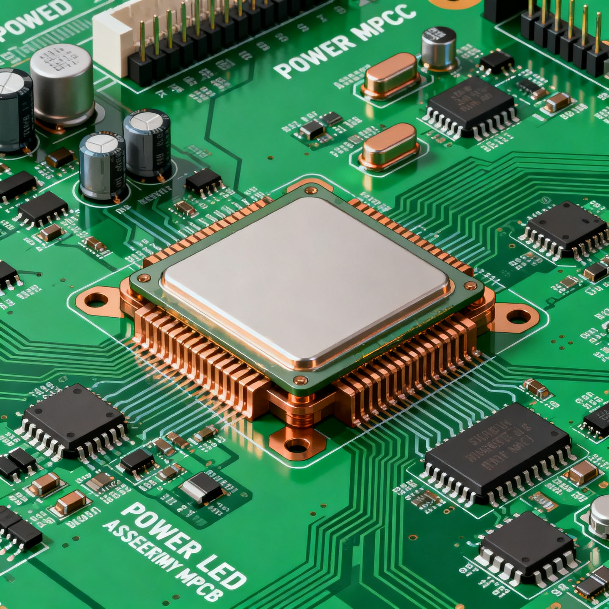
High Power LED PCB Assembly: A Practical Guide with Real Thermal Management Examples on 2oz Copper MCPCBs
High Power LED PCB Assembly: A Practical Guide with Real Thermal Management Examples on 2oz Copper MCPCBs When a 10°C Rise Halves Your LED Lifetime: Why Thermal Management Dictates Assembly Success Hi...
High Power LED PCB Assembly: A Practical Guide with Real Thermal Management Examples on 2oz Copper MCPCBs
When a 10°C Rise Halves Your LED Lifetime: Why Thermal Management Dictates Assembly Success
High-power LED assemblies live and die by a single number: junction temperature. A rule of thumb that every PCB designer and manufacturing buyer should internalize comes from thermal management specialists at HilPCB: every 10°C increase in junction temperature can halve the LED’s lifetime and cut light output by 5–8% [source]. An LED rated for 50,000 hours might fail within 5,000 hours if the thermal path isn’t engineered correctly—turning a product launch into a costly recall. For buyers sourcing high-power LED PCB assembly, this isn’t a theoretical risk; it’s a field failure that shows up in warranty claims, municipal lighting retrofits, and automotive headlamp modules.
The 2025 landscape demands multi-layered inspection to catch the defects that lead to thermal runaway. LTPCBA’s 2025 guide to LED PCBA underscores that AOI alone isn’t enough: automated optical inspection scans for missing LEDs, tombstoning, and solder bridges, but hidden joints under Chip-on-Board (COB) LEDs require X-ray inspection to verify underpad solder integrity. Thermal testing then validates that the entire heat sink and board stack-up performs under load. Without this triad—AOI, X-ray, and thermal cycling—a high-power LED board can pass initial functional test and still fail prematurely in the field.
JLCPCB’s practical assembly cases reinforce the same message: when you move into high-power LED design, metal-core PCBs (MCPCBs) are the only reliable option that delivers performance under that heat [source]. Standard FR4 boards simply cannot pull heat away fast enough, leading to accelerated lumen depreciation and delamination. Meanwhile, RingPCB’s work on high-power supply assemblies highlights the same thermal, EMI, and reliability challenges that plague LED drivers and power stages when thermal margins are squeezed. For engineers and buyers, the takeaway is clear: assembly success starts with choosing the right thermal substrate and verifying every joint, not just the ones you can see.
How 2oz Copper MCPCBs Pull Heat Away: The Thermal Path from Junction to Ambient
To appreciate why 2oz copper on an MCPCB matters, you need to follow the heat. The thermal path begins at the LED junction, travels through the die attach and lead frame, across the solder joint, into the copper circuit layer, through the dielectric, and finally into the aluminum or copper base plate. Each interface adds thermal resistance. The copper layer’s job is to spread heat laterally before it reaches the dielectric, reducing the heat flux density and lowering the temperature drop across the dielectric. A 2oz copper layer (70 µm thick) offers roughly twice the lateral thermal spreading capability of 1oz copper, which directly reduces hot spots under each LED footprint.
Metal-core PCBs rely on a thin dielectric layer with high thermal conductivity—typically 2 to 8 W/m·K, as noted in PCBSync’s comprehensive LED PCB guide. Compare that to standard FR4, where the glass-epoxy dielectric has a thermal conductivity of only about 0.3 W/m·K. The difference is an order of magnitude. When you combine a high-thermal dielectric with a thick copper circuit layer, you create a heat spreader that keeps the LED junction within safe limits even when ambient temperatures rise or multiple LEDs are packed tightly together. AllPCB’s dimension guidelines also remind us that board size and shape affect the thermal resistance to ambient, so the copper thickness must be evaluated in the context of the overall footprint and enclosure.
Panasonic’s ECOOL high-thermal laminates, detailed in PCBSync’s material guide, push dielectric thermal conductivity even higher, enabling LED lifetimes beyond 100,000 hours for municipal and industrial applications. These laminates, when paired with 2oz copper, create a thermal path that can handle continuous power densities that would destroy an FR4 board in minutes. The following table quantifies the thermal resistance differences you can expect for a typical high-power LED footprint.
| Board Stack-Up | Dielectric Thermal Conductivity (W/m·K) | Copper Thickness | Typical Thermal Resistance (Junction-to-Ambient, K/W)* | Notes |
|---|---|---|---|---|
| Standard FR4 (1.6 mm, 1oz Cu) | 0.3 | 1 oz (35 µm) | 45–60 | Only suitable for low-power indicator LEDs; rapid thermal runaway above 1 W. |
| Aluminum MCPCB, 1oz Cu | 2.0 | 1 oz (35 µm) | 12–18 | Good for medium-power arrays up to ~10 W; hot spots may appear with dense LED placement. |
| Aluminum MCPCB, 2oz Cu | 2.0 | 2 oz (70 µm) | 8–12 | Recommended for high-power LEDs 10–50 W; lateral spreading reduces peak temperatures significantly. |
| Aluminum MCPCB, 2oz Cu, High-Thermal Dielectric (e.g., Panasonic ECOOL) | 5–8 | 2 oz (70 µm) | 4–8 | Enables 50 W+ designs; extended lifetime past 100,000 hours when properly heatsinked. |
| Copper-Core MCPCB, 2oz Cu | 3–5 (typical dielectric) | 2 oz (70 µm) | 3–6 | Best thermal performance but higher cost and weight; used in extreme environments. |
*Values are approximate for a single medium-power LED (3–5 W) on a 25×25 mm board with natural convection. Actual values depend on board size, LED density, and heatsink.
The table makes the case for 2oz copper as the sweet spot for most high-power LED assemblies. The jump from 1oz to 2oz copper on the same MCPCB dielectric can reduce thermal resistance by 30–40%, which directly translates into lower junction temperatures and longer life. When you’re designing a 30 W streetlight module or a 15 W downlight, that margin often means the difference between a 50,000-hour product and a 25,000-hour one. The Panasonic ECOOL option pushes performance further, but even a standard 2oz aluminum MCPCB with a 2 W/m·K dielectric handles the majority of commercial and industrial LED applications reliably.
MCPCB Material Trade-offs: Aluminum vs. Copper Core, Dielectric Choices, and Real-World TIM Behavior
Choosing an MCPCB isn’t just about picking the highest thermal conductivity number. Cost, coefficient of thermal expansion (CTE), weight, and the behavior of the thermal interface material (TIM) between the board and the heatsink all influence long-term reliability. PCBSync’s LED PCB design guide recommends aluminum-core MCPCBs for most designs above 10 W, citing the best balance of thermal performance and cost. Copper-core boards offer roughly twice the thermal conductivity of aluminum but at a significant price premium and with added weight that can complicate mechanical mounting.
The dielectric layer is where much of the thermal resistance resides. Standard MCPCB dielectrics range from 1 to 3 W/m·K, while high-performance variants using boron nitride or alumina fillers reach 5–8 W/m·K. However, as Clemens Lasance’s classic paper on PCB thermal management for LED applications points out, real-world TIM behavior often deviates from datasheet values. Application-specific parameters—pressure applied, TIM thickness, surface flatness, and assembly process control—can dramatically alter the effective thermal resistance. Lasance emphasizes that standard ASTM D5470 tests may not reflect the actual pressure and thickness conditions in a factory assembly, so you must validate the TIM in your specific stack-up.
Fastturnpcbs’ layout guide adds another dimension: thermal cycling reliability. High-power LED boards experience repeated heating and cooling cycles that stress solder joints and the dielectric bond. Component clearances, copper balancing, and the CTE mismatch between the copper layer and the aluminum base must be considered. Aluminum has a CTE around 23 ppm/°C, while copper is about 17 ppm/°C. This mismatch, though smaller than with FR4, still creates shear stress on the dielectric during thermal cycling. Copper-core MCPCBs reduce this mismatch because the base and circuit layer are both copper, but at a cost that may not be justified for indoor or moderate-environment applications.
The comparison table below summarizes the key trade-offs, drawing on the real-world data from the sources cited.
| Material Option | Thermal Conductivity (W/m·K) | CTE (ppm/°C) | Relative Cost | Typical Wattage Range | Best Application |
|---|---|---|---|---|---|
| Aluminum MCPCB, standard dielectric (2 W/m·K) | 2.0 (dielectric) / 150 (base) | 23 (base) | $ (low) | 5–30 W | General LED lighting, downlights, track lights |
| Aluminum MCPCB, high-thermal dielectric (5–8 W/m·K) | 5–8 (dielectric) | 23 (base) | $$ (medium) | 30–80 W | Streetlights, high-bay fixtures, stadium lighting |
| Copper-core MCPCB, standard dielectric | 3–5 (dielectric) / 390 (base) | 17 (base) | $$$ (high) | 50–150 W | Automotive headlamps, UV curing, extreme ambient |
| FR4 with thermal vias (no metal core) | 0.3 (dielectric), vias improve spreading | 14–16 (x-y) | $ (lowest) | <5 W (with careful design) | Low-power decorative, indicator arrays |
Cost is relative and depends on order volume; “$” denotes lowest cost tier. Thermal conductivity values for dielectric layer; base metal conductivity listed separately. Data compiled from PCBSync LED PCB guide, PCBSync design guide, and Fastturnpcbs layout considerations.
For most buyers and engineers, the aluminum MCPCB with a 2–3 W/m·K dielectric and 2oz copper hits the optimal cost-performance point. If your design pushes past 50 W or operates in an ambient above 60°C, stepping up to a high-thermal dielectric or copper core becomes necessary. But don’t overlook the TIM: even the best MCPCB will overheat if the interface to the heatsink is starved of pressure or uses an incorrect grease thickness. Lasance’s advice to control pressure and thickness in production is not academic—it’s a practical requirement that prevents field failures.
Design and Assembly Checklist to Prevent Thermal Runaway in High-Power LED Boards
Thermal runaway in LED assemblies doesn’t happen because of one bad decision; it’s the accumulation of small oversights that choke the thermal path. The following checklist translates the research into actionable steps for engineers and buyers who need to sign off on a high-power LED PCB design and its assembly.
| Design/Assembly Parameter | Recommendation | Verification Method |
|---|---|---|
| Power supply margin | Verify at least 30% headroom above maximum LED load. | Bench test at max ambient and full dimming range; check for voltage sag. |
| Thermal vias under LEDs | Place filled and capped thermal vias directly under every LED thermal pad. | Cross-section micrograph; thermal imaging under load. |
| Copper thickness | Use 2oz copper on MCPCB as baseline for LEDs >3 W each. | Verify with fabricator’s stack-up report; measure trace cross-section on first article. |
| Inspection coverage | AOI for surface defects; X-ray for COB underpad solder; thermal cycling test for latent voids. | Per LTPCBA 2025 guide: AOI + X-ray + functional thermal test. |
| TIM application | Control pressure and thickness per ASTM D5470; use automated dispensing or pre-cut pads. | Measure bondline thickness on production samples; thermal impedance testing. |
| Thermal simulation | Run steady-state and transient thermal simulation before layout freeze. | Request simulation report from designer; correlate with physical thermocouple measurements. |
| Material compliance | Specify IPC-4101/104 for thermally conductive base materials; ask for Panasonic ECOOL datasheet if using high-thermal laminates. | Supplier certificate of conformance; cross-section analysis for dielectric thickness. |
| ESD and reverse polarity protection | Include TVS diodes and series Schottky or P-channel MOSFET for reverse battery protection. | Functional test with reverse voltage and ESD gun per IEC 61000-4-2. |
| Mechanical fit and 3D check | Verify board outline, mounting holes, and connector placement against enclosure 3D model. | 3D STEP model overlay; first-article mechanical fit test. |
This checklist isn’t theoretical. PCBSync’s design checklist echoes the same points: trace widths must meet current requirements, LED binning must be documented, and test points must be included for debugging. When you’re sourcing assembly, ask your partner whether they perform X-ray inspection as a standard step for COB LEDs and whether they can provide thermal impedance data for the TIM application. At NovaPCBA, high-power LED PCB assembly on 2oz copper MCPCBs includes full X-ray inspection, thermal cycling validation, and support for Panasonic ECOOL and other high-thermal laminates, ensuring that the thermal path you designed is the thermal path you get in production.
One more practical tip: if you’re aiming for a 100,000-hour lifetime, the Panasonic ECOOL laminates described in PCBSync’s material guide are worth the premium. Municipalities and industrial users calculate total cost of ownership over decades, and the extended life drastically reduces replacement and maintenance costs. Just make sure your assembly partner has experience with these materials, as the lamination and drilling parameters differ from standard MCPCBs.
High-Power LED PCB Assembly: Questions Engineers and Buyers Ask Before Signing Off
Q: How can I verify the actual thermal conductivity of an MCPCB dielectric before production?
A: Request a datasheet that references ASTM D5470 testing and ask for a cross-section micrograph of the dielectric layer. Reputable suppliers will provide thermal impedance curves; compare these against your simulation requirements. If the supplier cannot produce these documents, treat the thermal conductivity claim as unverified and add extra margin to your thermal design.
Q: What inspection techniques are essential for hidden COB LED solder joints?
A: X-ray inspection is mandatory for COB LEDs with underpad solder, as AOI cannot see beneath the package. Complement X-ray with thermal cycling tests (e.g., -40°C to +125°C, 100 cycles) to catch latent voids that only appear under stress. Some manufacturers also use acoustic microscopy for initial qualification, but X-ray remains the production-line gold standard.
Q: When is 2oz copper on an MCPCB not enough for high-power LEDs?
A: If the LED array exceeds 50 W on a small board area or ambient temperatures are above 60°C, 2oz copper may still create hotspots. In such cases, consider 3oz copper or a copper-core MCPCB, and always validate with thermal simulation. The lateral spreading capability of 2oz copper has limits; once the heat flux density exceeds about 10 W/cm² at the board surface, you need a thicker copper layer or a higher-conductivity dielectric.
Q: Can I place high-power LED drivers and LEDs on the same MCPCB?
A: It is possible but risky due to driver heat affecting LED junction temperature. The driver’s switching losses can add 5–10 W of heat directly into the board. Separate the driver onto a conventional FR4 board or use thermal isolation slots in the MCPCB. If co-location is unavoidable, derate the LED current by at least 20% and simulate the combined thermal load to ensure junction temperatures stay within limits.
Q: What lead time should I expect for a custom 2oz copper MCPCB stack-up?
A: Typical lead times range from 2 to 4 weeks for prototypes, depending on the dielectric material availability. Standard Panasonic ECOOL laminates may be stocked by major fabricators, while exotic high-thermal dielectrics can add 1–2 weeks. Always confirm with your fabricator before finalizing the BOM, and consider ordering pre-production samples to validate the stack-up before committing to a full production run.
Q: How do I calculate the required copper area for a given LED wattage?
A: Start with the LED’s thermal resistance (junction-to-case) and the maximum allowable junction temperature. Use the formula: Rth(total) = (Tj – Ta) / Pd, where Tj is max junction temp, Ta is max ambient, and Pd is power dissipation. Subtract the LED’s internal Rth(j-c) and the TIM resistance to find the required PCB thermal resistance. From the MCPCB datasheet, determine the copper area needed to achieve that resistance, adding a 30% safety margin. Most LED manufacturers provide PCB land pattern recommendations that include minimum copper area for a given wattage; use these as a starting point and verify with simulation.
References & Further Reading
- 2025 Guide to PCBA LED Design & Assembly – LTPCBA
- LED PCB Heat Dissipation: Thermal Management Solutions – HilPCB
- Thermal Management Techniques for High-Power LED PCBs – JLCPCB
- PCB and Assembly Services for High Power Supply Applications – RingPCB
- Basics of (PCB) Thermal Management for LED Applications – Clemens J.M. Lasance
- LED PCB Design: SMD, Light Circuits & VU Meter Layout Guide – PCBSync
- PCB LED Design Guide: Layout, Routing, and Thermal Management – Fastturnpcbs
- LED PCB: Complete Guide to Types, Design, Materials & Applications – PCBSync
- PCB Materials for LED Lighting: Panasonic ECOOL High-Thermal Laminates – PCBSync
- Standard PCB Dimensions for LED Lighting Applications – AllPCB
When your design moves from prototype to production, having an assembly partner who understands the thermal stakes makes all the difference. At NovaPCBA, we specialize in high-power LED PCB assembly on 2oz copper MCPCBs, with in-house X-ray inspection, thermal cycling validation, and experience across standard and high-thermal dielectrics. Whether you’re building a 10 W downlight or a 100 W stadium module, we help ensure your thermal path holds up for the long haul.