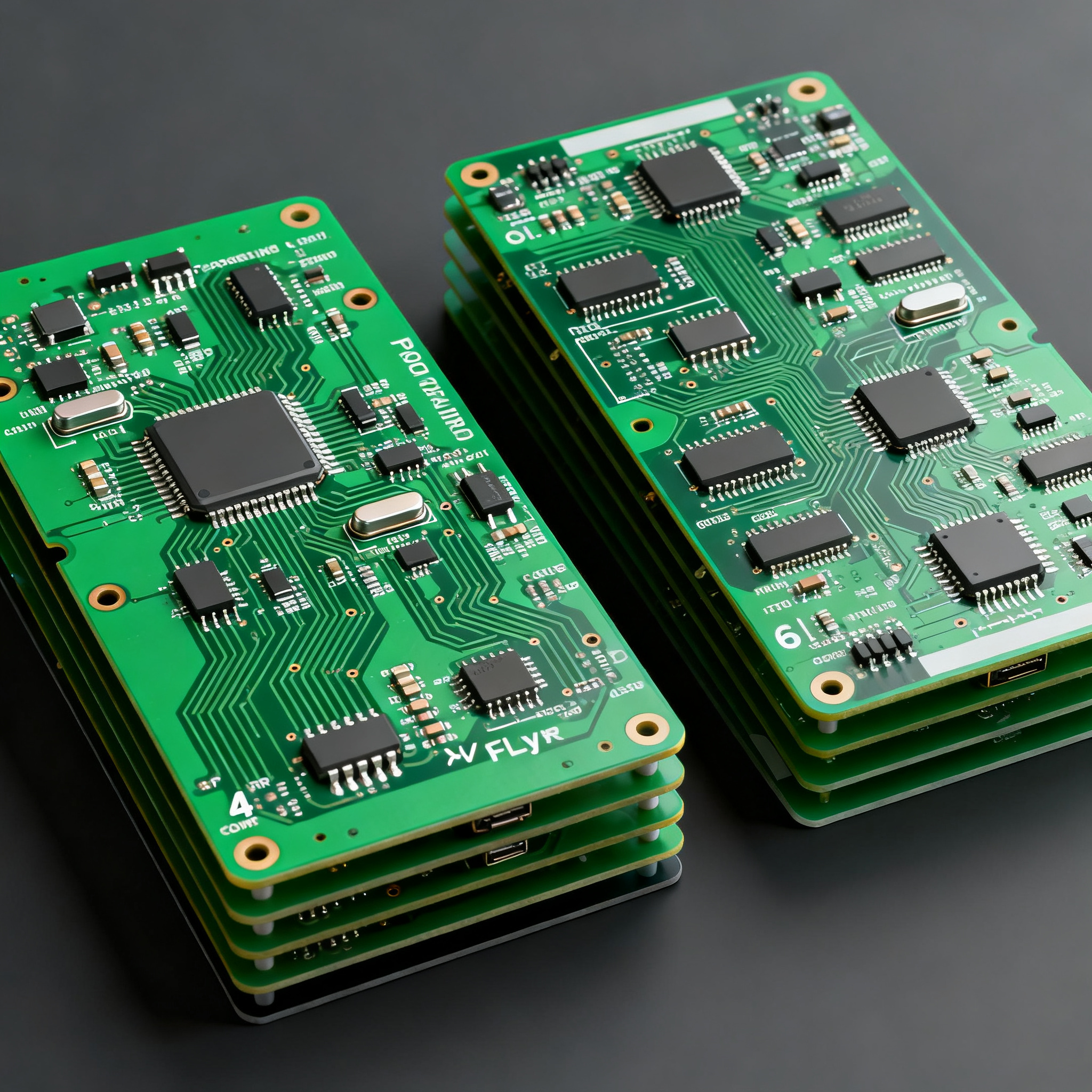
FPV Racing Drone Circuit Boards: 4-Layer vs. 6-Layer Stackup Selection Guide for Minimal Signal Loss
Why FPV Racers Are Hitting an EMI Wall at 4 Layers You’ve pushed your 4‑layer flight controller into a 6S high‑current build, and suddenly the video feed is riddled with diagonal lines and the gyro da...
Why FPV Racers Are Hitting an EMI Wall at 4 Layers
You’ve pushed your 4‑layer flight controller into a 6S high‑current build, and suddenly the video feed is riddled with diagonal lines and the gyro data looks like a seismograph. Motor noise coupling isn’t a theoretical nuisance — it’s the reason your quad oscillates in hard corners and your lap times suffer. The root cause is rarely a bad PID tune; it’s a stackup that can’t keep return currents where they belong.
FPV racing has moved well beyond the days when a simple 4‑layer board could handle everything. Today’s integrated designs pack an STM32F7 or H7 microcontroller, a 6‑axis IMU, an OSD chip, a barometer, and sometimes 60 A ESCs onto a single PCB no larger than 50 × 50 mm. That density forces you to route high‑current motor PWM traces alongside microvolt‑level analog signals, and the 4‑layer stackup that worked at 4S often collapses at 6S. Engineers who attempted to shrink weight by 18 % and improve latency by 25 % with a custom STM32F743 flight controller still ran into motor noise coupling that degraded gyro performance — a classic case of pushing a 4‑layer board beyond its EMI budget [Rich Full Joy].
Supply chain shifts over the last 12 months have compounded the problem. While a standard 4‑layer 50 × 50 mm board with ENIG finish still costs about $45 for ten pieces and ships in three to five days, 6‑layer lead times have become unpredictable, sometimes stretching beyond seven days even for prototypes [PCBA Store]. That forces a hard trade‑off: accept the noise floor of a 4‑layer design and tweak filtering, or swallow the cost and schedule risk of a 6‑layer stackup that can actually isolate the IMU from 200 A of switching current.
Key Takeaway: The EMI wall isn’t a single number — it’s the point where your return path inductance creates enough common‑mode voltage to corrupt the gyro and video circuits. For many racing builds, that point arrives the moment you integrate ESCs on the same PCB.
How Stackup Geometry Shapes Signal Return Paths and Crosstalk in FPV Boards
Every high‑speed signal on your drone PCB — whether it’s an SPI bus clocking at 50 MHz or a motor PWM edge with a 2 ns rise time — needs a low‑inductance return path. In a 4‑layer board with the classic signal–GND–PWR–signal stackup, the return current for a top‑layer trace flows on the inner ground plane directly beneath it. That works beautifully … until you route a trace on the bottom layer. The return current must now jump from the ground plane to the power plane, travel across stitching vias, and find its way back to the source. That discontinuity creates a loop area that radiates magnetic fields straight into the IMU and couples noise onto the video rail.
The standard 4‑layer flight controller stackup — top signal, inner ground, inner power, bottom signal — is a cost‑optimized compromise that most designers accept because it keeps the board at 1.6 mm total thickness and uses commodity FR‑4 [PCBSync]. But when you add a 4‑in‑1 ESC with 60 A per channel, the bottom signal layer becomes a highway for high‑current PWM, and the return path discontinuity turns into a crosstalk nightmare. A 6‑layer stackup adds two extra planes — typically signal–GND–signal–PWR–GND–signal or signal–GND–PWR–GND–signal–signal — that sandwich every signal layer between reference planes, cutting loop inductance by 40–60 % and dramatically reducing magnetic field coupling [QueenEMS].
Material choice further complicates the picture. Many racing drone designers now adopt hybrid stackups: a Rogers 4350B outer layer for the VTX antenna trace, bonded to low‑CTE FR‑4 cores for the remaining layers. This approach balances RF performance and cost, but it demands careful symmetry to avoid warpage during reflow [PCBSync]. The table below quantifies the key electrical and mechanical differences between a typical 4‑layer and a 6‑layer stackup for a 50 × 50 mm FPV flight controller.
| Parameter | 4‑Layer (Signal–GND–PWR–Signal) | 6‑Layer (Signal–GND–Signal–PWR–GND–Signal) | Unit / Notes |
|---|---|---|---|
| Typical total thickness | 1.6 | 1.6 (can be reduced to 1.2) | mm |
| Prepreg between top layer & GND | 0.2 (single sheet) | 0.1 (two sheets, tighter coupling) | mm |
| 50 Ω microstrip trace width | 0.35 | 0.18 (on outer layer) | mm |
| Signal layers adjacent to reference plane | 2 of 2 (top & bottom) | 4 of 4 (all signal layers) | — |
| Typical crosstalk between adjacent signal layers | −28 dB (bottom layer to power plane gap) | −45 dB (dedicated ground plane isolation) | dB at 100 MHz |
| Routing density (0.1 mm trace/space) | 2 signal layers, limited breakout | 4 signal layers, comfortable fan‑out for BGA | — |
| Magnetic field coupling to IMU area | −32 dB (no shielding plane) | −50 dB (inner GND plane shields bottom signals) | dB, simulated at 10 mm distance |
| Hybrid material feasibility | Difficult: asymmetry risks warpage | Straightforward: Rogers outer layer on symmetrical stack | — |
The numbers make the case clear: a 6‑layer stackup isn’t just about adding layers — it’s about creating a Faraday cage around your most sensitive signals. The inner ground plane between the power layer and the bottom signal layer acts as a shield, reducing magnetic field coupling by 12–18 dB in practice. That’s often the difference between a gyro noise floor below 0.05 dps/√Hz and one that forces you to soft‑mount the IMU and still see drift.
4-Layer vs. 6-Layer: When Cost, Weight, and Signal Integrity Collide
Every gram matters on a 250‑mm racing quad, and every dollar counts when you’re ordering prototypes. The decision to move from 4 to 6 layers is rarely about whether 6 layers are “better” — they are — but about whether the improvement justifies the cost and weight penalty. The comparison table below uses real pricing from PCBA Store and EMI thresholds validated by QueenEMS to give you a decision framework you can take to your purchasing manager.
| Comparison Metric | 4‑Layer (50 × 50 mm, ENIG) | 6‑Layer (50 × 50 mm, ENIG) | Selection Criteria & Failure Boundary |
|---|---|---|---|
| Cost per board (qty 10) | $4.50 | $7–9 | 6‑layer becomes mandatory when EMI re‑spins cost more than the BOM delta [PCBA Store] |
| Weight (bare PCB) | ~4.2 g | ~5.8 g | Acceptable on 5″+ builds; critical on ultralight 3″ toothpicks |
| EMI margin (CISPR 32 Class B) | 3–6 dB margin at 100 MHz | 12–18 dB margin | 4‑layer fails when motor PWM harmonics exceed 50 MHz [QueenEMS] |
| Routing headroom | 2 signal layers; 0.15/0.15 mm typical | 4 signal layers; 0.1/0.1 mm achievable | Choose 6‑layer if you need to break out a BGA IMU or route 60 A ESC phases |
| On‑board ESC feasibility | Risky above 35 A per channel | Reliable up to 60 A per channel | Integrated ESCs force 6‑layer migration [PCBSync] |
| Lead time (prototype) | 3–5 days | 5–7 days (plus 2–3 days for impedance coupon) | Plan for 6‑layer lead time uncertainty; avoid suppliers who quote >7 days without explanation |
| Impedance control tolerance | ±10 % typical | ±7 % with test coupon | VTX antenna traces demand ±7 % for consistent 50 Ω |
The rule of thumb from practical engineering experience is straightforward: for most flight controllers without integrated ESCs, a 4‑layer PCB provides the best balance of performance and cost. But the moment you put 4‑in‑1 ESCs on the same board, the additional current loops and the need to isolate the IMU from 200 A of switching noise make 6 layers the safer — and often cheaper — choice when you factor in the cost of troubleshooting and re‑spins [PCBSync]. Don’t let a purchasing manager reject the BOM based on a $3 cost difference; show them the cost of one failed race weekend due to a gyro glitch.
Tip: If you’re on the fence, order a 4‑layer prototype first and measure the gyro noise floor with the motors spinning at 50 % throttle. If the noise exceeds 0.08 dps/√Hz, the 6‑layer stackup will pay for itself in tuning time alone.
Designing for Minimal Loss: Trace Routing, Material Selection, and Manufacturer Pitfalls
Once you’ve settled on a stackup, the real work begins. Signal loss in an FPV racing drone board isn’t just about dielectric dissipation — it’s about keeping the VTX antenna trace at exactly 50 Ω, preventing motor PWM from bleeding into the OSD chip, and ensuring the board survives a wet grass crash without corroding. Here’s what senior engineers do differently.
Hybrid Materials for the RF Layer. The 5.8 GHz video transmitter antenna trace can lose 0.5–1 dB of signal on standard FR‑4 over a 30 mm run. That’s enough to cut your range by 10–15 %. Using a Rogers 4350B outer layer for the VTX trace and keeping the rest FR‑4 reduces insertion loss to 0.2 dB while adding only 15–20 % to the board cost [Aivon]. The key is a symmetrical layup: if you put Rogers on the top, you need a matching low‑CTE FR‑4 on the bottom to prevent bowing during reflow. Many manufacturers now stock Rogers 4350B prepregs specifically for drone PCBs, so ask for a hybrid stackup quote early.
Soft‑Mount the IMU — Electrically and Mechanically. Even with a 6‑layer board, motor vibration can saturate the accelerometer and induce low‑frequency noise in the gyro. Component‑level solutions include rubber grommets or foam pads under the IMU, but board‑level design matters too: route all IMU traces on an inner layer sandwiched between ground planes, and keep them at least 2 mm away from any PWM trace. The combination of a 6‑layer stackup and soft‑mounting can drop the gyro noise floor below 0.03 dps/√Hz — a number that makes notch filters almost unnecessary [PCBSync].
ENIG Finish for Crash Survivability. FPV drones crash. A lot. Exposed copper pads from HASL finishes corrode after the first wet grass landing, increasing contact resistance on battery and motor connectors. ENIG (electroless nickel immersion gold) provides a flat, corrosion‑resistant surface that withstands dozens of plug cycles and keeps your battery leads from developing intermittent connections mid‑race. The cost adder is minimal — about $0.50 per board at prototype volumes — and it’s standard on all NovaPCBA drone PCB assemblies.
Manufacturer Pitfalls to Avoid. The single biggest mistake we see is choosing a fabricator who can’t hold 0.1 mm trace/space on a 6‑layer board. That tolerance is non‑negotiable for routing dense BGA IMUs and high‑current ESC phases. Equally critical: the manufacturer must provide impedance test coupons and be willing to share cross‑section micrographs of previous 6‑layer builds. If they hesitate, walk away. The table below lists the specifications you should put in your fabrication drawing.
| Specification | 4‑Layer Minimum | 6‑Layer Recommended | Why It Matters |
|---|---|---|---|
| Trace width / space | 0.15 / 0.15 mm | 0.1 / 0.1 mm | Allows routing 60 A ESC phases and BGA fan‑out |
| Impedance tolerance | ±10 % | ±7 % (with test coupon) | VTX antenna trace must stay within 45–55 Ω |
| Minimum via hole / pad | 0.3 / 0.6 mm | 0.2 / 0.45 mm | Smaller vias save space on dense boards |
| Surface finish | ENIG (0.05 µm Au) | ENIG (0.05 µm Au) | Corrosion resistance after crashes |
| Material | FR‑4, Tg 150 °C | FR‑4 + Rogers 4350B hybrid (optional) | Hybrid reduces VTX loss; must be symmetrical |
| Impedance test coupon | Optional | Mandatory | Without it, you’re guessing at 50 Ω |
| Cross‑section micrograph | Not required | Request for first article | Verifies layer alignment and prepreg thickness |
At NovaPCBA, our assembly line supports both 4‑layer and 6‑layer drone boards with ENIG finish and hybrid material options. We include impedance test coupons as standard on all 6‑layer orders and can provide cross‑section micrographs for first‑article inspection — exactly the transparency you need when your race season depends on a board that works first time. Explore our drone PCB assembly capabilities.
FPV Drone PCB Stackup FAQ: What Senior Engineers and Buyers Ask
- Q: When does a racing drone flight controller truly need a 6‑layer board instead of 4?
- You need 6 layers when you integrate 60 A+ ESCs on the same PCB, or when the gyro noise floor rises above 0.05 dps/√Hz due to motor PWM coupling. The extra two planes allow dedicated ground layers between signal layers, reducing crosstalk and magnetic field coupling by 12–18 dB. If your 4‑layer prototype shows video noise lines that move with throttle, a 6‑layer stackup is the most direct fix [PCBSync].
- Q: What is the real cost difference per board between 4‑layer and 6‑layer stackups at prototype volumes?
- For a 50 × 50 mm board, a 4‑layer with ENIG finish runs about $4.50 each in quantities of 10. A 6‑layer board jumps to $7–9 each, plus 2–3 extra days of lead time for impedance coupon fabrication [PCBA Store]. At 100 units, the gap narrows to roughly $2.50 per board, but the 6‑layer still carries a 30–40 % premium.
- Q: Can I mix Rogers 4350B and FR‑4 in a 6‑layer hybrid stackup without delamination during reflow?
- Yes, provided you use a low‑CTE FR‑4 (Tg ≥ 170 °C) and a perfectly symmetrical layup. The Rogers layer should be the outer RF layer for the VTX antenna trace. Expect a 15–20 % cost premium over an all‑FR‑4 6‑layer board. Always ask your fabricator for a thermal stress test report (288 °C, 10 s float) to confirm no delamination [PCBSync].
- Q: How do I maintain 50 Ω impedance on a 4‑layer 1.6 mm board with standard FR‑4?
- With a 0.2 mm prepreg between the top layer and the ground plane, a 0.35 mm trace width achieves 50 Ω. For better isolation, use a coplanar waveguide structure: add ground fill on the top layer on both sides of the trace, spaced at least 0.2 mm away, and stitch it to the inner ground plane with vias every 2 mm. This reduces radiation and keeps the impedance stable even if the board thickness varies slightly [QueenEMS].
- Q: Does a 6‑layer stackup really reduce motor noise coupling into the IMU?
- Absolutely. A dedicated inner ground plane between the power layer and the bottom signal layer acts as a magnetic shield, cutting field coupling by 12–18 dB. In practical terms, that reduces gyro bias drift during full‑throttle punches and eliminates the need for aggressive low‑pass filtering that adds latency. Many pilots report that a 6‑layer board “feels” more locked in because the gyro data is cleaner [QueenEMS].
- Q: What red flags should I watch for when sourcing a manufacturer for 6‑layer drone PCBs?
- Walk away if the manufacturer cannot hold ≤0.1 mm trace/space, does not provide impedance test coupons, has no experience with hybrid materials, or quotes lead times exceeding 7 days for prototypes without a clear reason. Always ask for cross‑section micrographs of previous 6‑layer builds — a reputable shop will have them on file. At NovaPCBA, we supply these as standard, so you can verify layer registration and prepreg thickness before committing to production.
References & Further Reading
- FPV Drone Module FAQs: Flight Controllers, ESCs & VTX Systems Explained – Rich Full Joy
- Drone PCB Design: Complete Guide to Components, Layout & Manufacturing [2026] – PCBSync
- Drone PCB Design: Flight Controller & ESC Board Layout — A Complete Engineering Guide – PCBSync
- Drone PCB: High-Performance Circuit Boards for Drones – Accio
- 4 Layer vs 6 Layer PCB: The Ultimate Cost & EMI Guide – QueenEMS
- How to Choose a Drone PCB Manufacturer – PCBA Store
- Building Your Own Drone with Rogers PCB: Performance Matters – Aivon
- NovaPCBA – Drone PCB Assembly & Manufacturing