Flexible PCB Design Guidelines: Key Considerations for High-Density Applications
Flexible PCB Design Guidelines: Key Considerations for High-Density Applications table { border-collapse: collapse; width: 100%; margin: 20px 0; } th, td { border: 1px solid #ddd; padding: 8px; } th {...
Introduction
In the rapidly evolving world of electronics, flexible printed circuit boards (PCBs) have become crucial for high-density applications. These boards offer the versatility needed for modern devices, accommodating complex designs while reducing size and weight. As the demand for compact, efficient electronics grows, understanding the design and implementation of flexible PCBs becomes increasingly important for engineers and manufacturers.
Technical Overview
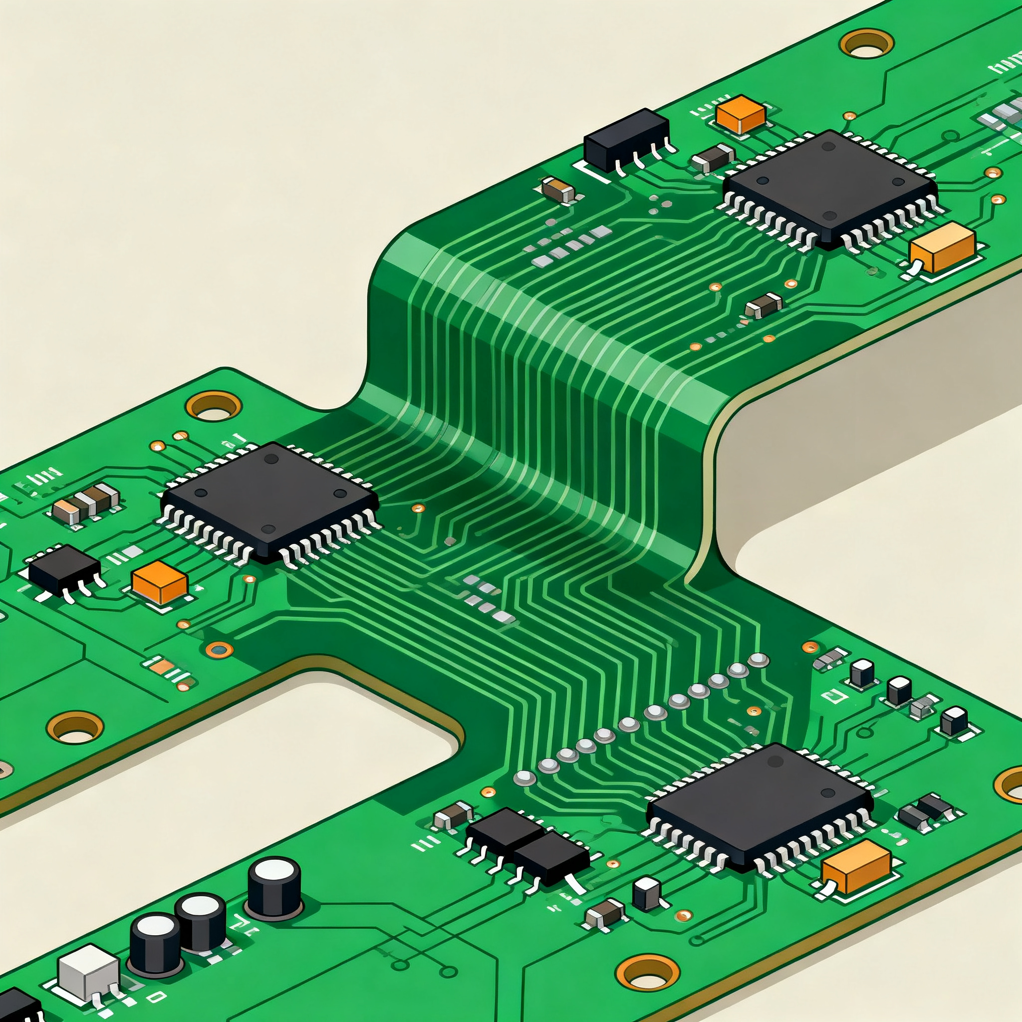
Flexible PCBs are a type of circuit board designed to bend and flex, providing a solution for compact and intricate electronic designs. They consist of a thin, flexible substrate material, typically polyimide, which allows them to fit into tight spaces and withstand mechanical stress. The architecture of these boards enables the integration of multiple layers, providing enhanced functionality and connectivity. Key principles in flexible PCB design include understanding the material properties, trace layout, and the impact of bending on signal integrity. By adhering to industry standards such as those from IPC, engineers can ensure reliable performance in high-density applications.
Detailed Specifications
Understanding the specifications of components used in flexible PCB design is critical. These specifications, often detailed in datasheets, include CPU speed, memory, and power requirements, which guide the selection and integration of components. This ensures optimal performance and longevity of the final product.
| Specification | Details | Comments |
|---|---|---|
| CPU Speed | 2.4 GHz | High performance for intensive applications |
| Memory | 16 GB DDR4 | Ample memory for multitasking |
| Peripherals | USB 3.0, HDMI | Supports various external devices |
| Power | 5V, 3A | Efficient power usage |
| Package | BGA | Compact and suitable for high-density |
| Storage | 512 GB SSD | Fast data access and retrieval |
| Connectivity | Wi-Fi 6, Bluetooth 5.0 | Advanced wireless communication |
| Operating Temperature | -40°C to 85°C | Wide range for various environments |
| Dimensions | 100 mm x 75 mm | Compact size for flexible integration |
| Layer Count | 6 | Multiple layers for complex designs |
| Material | Polyimide | Durable and flexible substrate |
| Signal Integrity | High | Ensures reliable data transmission |
Key Takeaways from the Specifications
The specifications outlined in the table highlight crucial aspects of component selection for flexible PCB design. The CPU speed and memory capacity are pivotal for determining the processing capability and efficiency of the system. The power requirements ensure that the board operates within safe and efficient limits, while the package type (BGA) is chosen for its compactness, making it ideal for high-density applications. The choice of materials and operating temperature range further supports the board’s adaptability in diverse environments, ensuring durability and performance.
| Characteristic | Specification | Details |
|---|---|---|
| Operating Voltage | 3.3V | Standard for low-power applications |
| Max Current | 1.5A | Handles moderate power loads |
| Clock Speed | 1 GHz | Suitable for fast data processing |
| I/O Pins | 32 | Ample for multiple peripherals |
| Input Capacitance | 10 pF | Low capacitance for high-speed signals |
| Output Drive Strength | 8 mA | Ensures strong signal transmission |
| ESD Protection | ±15 kV | Robust against electrostatic discharge |
| Leakage Current | 1 μA | Minimal leakage for power efficiency |
| Propagation Delay | 5 ns | Fast signal propagation |
| Power Dissipation | 0.5 W | Low for energy-efficient operation |
| Thermal Resistance | 30°C/W | Effective heat dissipation |
| Noise Margin | 1.2V | High immunity to noise |
Practical Implications
The electrical characteristics table provides insights into the operational limits and capabilities of the components used in flexible PCBs. Operating voltage and current define the power requirements, which are crucial for maintaining efficiency and preventing overheating. The clock speed and propagation delay affect the processing speed and data transfer rates, essential for high-performance applications. ESD protection and leakage current are vital for reliability and energy efficiency, ensuring that the board can withstand external interferences and minimize power loss.
| Application | Configuration | Benefits |
|---|---|---|
| Wearable Devices | Single Flex Layer | Lightweight and comfortable |
| Automotive | Multi-Layer Flex | Handles complex systems |
| Medical Equipment | High Reliability | Critical for patient safety |
| Consumer Electronics | Compact Design | Space-saving |
| Industrial Controls | Robust Build | Withstands harsh conditions |
| Aerospace | Lightweight Materials | Reduces payload |
| Communication Devices | High-Speed Signals | Ensures fast connectivity |
| Robotics | Flexible Configuration | Adapts to movement |
Application Guidelines
The application comparison table demonstrates the versatility of flexible PCBs across various industries. For wearable devices, the single flex layer offers a lightweight solution, enhancing user comfort. In automotive and aerospace sectors, multi-layer configurations provide the necessary complexity without adding weight. Medical equipment benefits from high reliability, ensuring patient safety. Each application underscores the need for careful selection of materials and design configurations to meet specific industry requirements, emphasizing the importance of flexibility and adaptability in modern electronic design.
Design Considerations
Designing flexible PCBs for high-density applications involves several critical considerations. First, understanding the mechanical properties of materials like polyimide is essential, as these impact the board's ability to bend without damaging the circuitry. Trace layout is another key factor, where minimizing trace lengths and optimizing routing paths help maintain signal integrity. It's also important to consider the thermal management of the board, ensuring that heat dissipation is adequate to prevent overheating. Adhering to IPC standards can guide designers in achieving high-quality and reliable boards. Furthermore, collaboration with manufacturers early in the design process can help identify potential challenges and streamline production, ensuring the final product meets performance and reliability expectations.
Step-by-Step Implementation
- Define Requirements: Begin by outlining the specific needs of your application, including size, flexibility, and environmental conditions.
- Select Materials: Choose suitable materials that provide the necessary flexibility and durability. Polyimide is commonly used for its excellent thermal and mechanical properties.
- Design Schematic: Use CAD tools to create a detailed schematic that outlines the electrical connections and component placements.
- Layout Design: Optimize the PCB layout by minimizing trace lengths and ensuring proper routing to maintain signal integrity. Consider via placement to facilitate multi-layer connections.
- Thermal Management: Incorporate thermal vias and heat sinks as needed to manage heat dissipation effectively.
- Prototype Testing: Fabricate a prototype and conduct thorough testing to identify any design flaws or performance issues.
- Iterate and Refine: Based on test results, refine the design to address any identified issues and optimize performance.
- Finalize Design: Once testing is complete and the design is validated, finalize the design for mass production.
Common Issues & Solutions
- Signal Integrity Loss: Use proper trace width and spacing, and consider differential pairs for high-speed signals.
- Excessive Flexing: Limit the bend radius and avoid sharp bends to prevent damage to the circuit.
- Thermal Management: Implement adequate cooling solutions such as thermal vias and heat sinks to manage heat dissipation.
- Material Delamination: Ensure proper bonding techniques and use materials with compatible coefficients of thermal expansion.
- Manufacturing Defects: Collaborate closely with manufacturers to adhere to design-for-manufacturability principles and perform regular quality checks.
- EMI Interference: Implement shielding techniques and maintain proper grounding to minimize electromagnetic interference.
Applications & Use Cases
Flexible PCBs are utilized in a wide array of applications, reflecting their versatility and adaptability. In consumer electronics, they enable compact designs in smartphones and tablets. The automotive industry leverages them for complex systems that require reliability under varying conditions. Medical devices benefit from their light weight and durability, crucial for patient monitoring equipment. In aerospace, their lightweight nature reduces payload, while in robotics, their flexibility accommodates dynamic movements. These examples underscore the importance of flexible PCBs in advancing technology across industries.
Selection & Sourcing Guide
When selecting components for flexible PCB design, consider factors such as performance requirements, environmental conditions, and compatibility with other components. Utilize resources like IC Online for sourcing, ensuring access to a wide range of components with detailed specifications and datasheets. Collaborate with manufacturers to ensure that selected components meet quality and reliability standards, aligning with the overall design objectives.
FAQ
- What are flexible PCBs? Flexible PCBs are circuit boards designed to bend and flex, offering versatility for compact electronic designs.
- Why use flexible PCBs? They provide solutions for space-constrained applications, offering durability and adaptability.
- What materials are used? Polyimide is commonly used for its excellent thermal and mechanical properties.
- How to ensure signal integrity? Optimize trace layout, use differential pairs, and maintain proper grounding.
- What are common design challenges? Managing signal integrity, thermal dissipation, and mechanical stress are key challenges.
- How to prevent material delamination? Use proper bonding techniques and compatible materials.
- What standards apply? IPC standards guide the design, assembly, and inspection of flexible PCBs.
- How to manage thermal issues? Implement cooling solutions such as thermal vias and heat sinks.
- What is the role of manufacturers? Collaborating with manufacturers ensures design-for-manufacturability and quality adherence.
- Where to source components? Utilize platforms like IC Online for a comprehensive selection of components.
Conclusion
Flexible PCBs are essential for modern high-density applications, offering the adaptability and performance required in various industries. By understanding the specifications, electrical characteristics, and application guidelines, engineers can design effective solutions that meet the demands of today's technology. Adhering to industry standards and collaborating with manufacturers further enhances the reliability and quality of flexible PCB designs, driving innovation and efficiency in electronics.