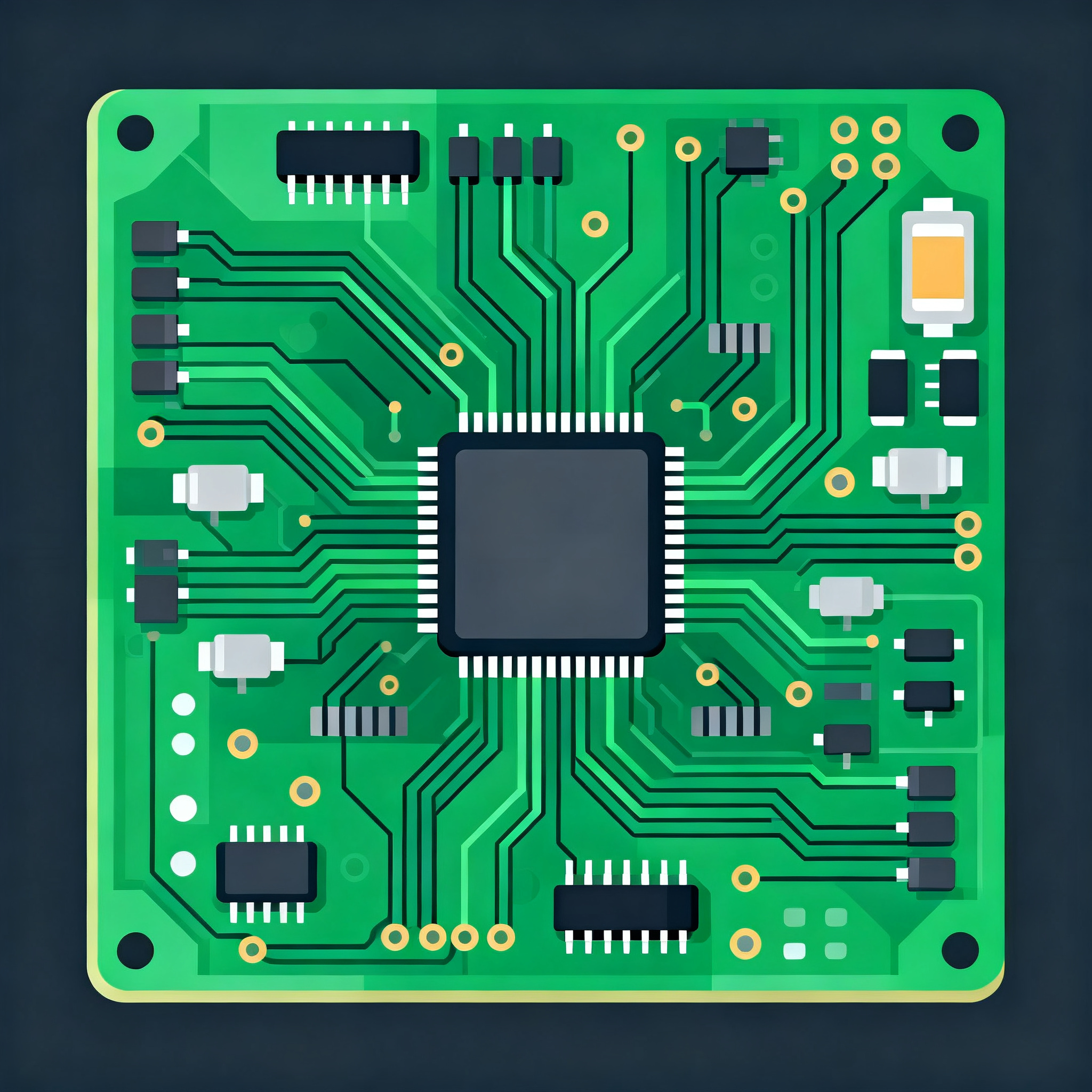
Cost Optimization Tips for High-Precision Medical PCB Fabrication: Balancing 2 mil Trace/Space and Impedance Control on 4-Layer Boards
Cost Optimization Tips for High-Precision Medical PCB Fabrication: Balancing 2 mil Trace/Space and Impedance Control on 4-Layer Boards When 2 mil Trace/Space on a 4-Layer Board Becomes a Cost Tightrop...
Cost Optimization Tips for High-Precision Medical PCB Fabrication: Balancing 2 mil Trace/Space and Impedance Control on 4-Layer Boards
When 2 mil Trace/Space on a 4-Layer Board Becomes a Cost Tightrope
Medical devices continue to shrink, pushing PCB designers toward 2 mil (0.05 mm) trace and space geometries on standard 4‑layer FR‑4 platforms. While this density packs more functionality into a wearable monitor, hearing aid, or single‑use sensor, it also turns fabrication into a high‑wire act. The moment you specify 2 mil lines on a 4‑layer board, you’re asking the fabricator to operate at the edge of conventional subtractive etching, where registration, undercut, and impedance control all become cost multipliers.
The primary cost drivers aren’t the raw materials—they’re yield and re‑spin risk. To reliably image 2 mil traces, a shop must use laser direct imaging (LDI) instead of traditional phototools, and tightly control etch uniformity across the panel. Even a 0.2 mil over‑etch can blow out a 2 mil line, turning a 50 Ω controlled‑impedance trace into a 60 Ω path that fails signal integrity testing. Registration between layers must stay within ±1 mil, which demands precision lamination fixturing and often a move to sequential lamination cycles. These process steps increase the cost per panel by 30–50% compared to a 4‑layer board with 5 mil rules, and scrap rates can climb if the fabricator hasn’t dialed in the process.
This is where early collaboration with a fabricator that understands medical requirements pays for itself. A partner like Nova PCBA can review your stackup before you freeze the design, flagging impedance discontinuities and suggesting minor tweaks—such as adjusting dielectric thickness or swapping prepreg styles—that preserve performance while improving manufacturability. Following IPC‑2221 design guidelines for conductor spacing and impedance formulas helps, but the real savings come from aligning your design intent with the fabricator’s proven process window. Without that alignment, a 2 mil board can easily become a prototype that never reaches production.
How 4-Layer Stackup and Dielectric Selection Dictate Impedance and Cost
On a 4‑layer board, the stackup directly determines how wide your 50 Ω single‑ended traces must be and how much the board will cost to fabricate. The classic signal‑ground‑power‑signal arrangement sandwiches two inner planes between outer signal layers, but the thickness of the core and prepreg dielectrics is what makes or breaks a 2 mil design. Thinner dielectrics let you hit target impedance with narrower traces, which sounds perfect for high density—until you factor in the manufacturing challenges they introduce.
Consider two common 4‑layer configurations for medical PCBs. The table below compares a 4‑mil core stackup (thin) with an 8‑mil core stackup (thicker), both using standard FR‑4 with a Dk of 4.2–4.5. The trace width required for 50 Ω on the outer layers drops dramatically as the distance to the reference plane shrinks, but the fabrication cost moves in the opposite direction.
| Stackup Parameter | 4‑mil Core (Thin Dielectric) | 8‑mil Core (Thicker Dielectric) | Cost & Yield Impact |
|---|---|---|---|
| Layer sequence | Top signal / GND plane / PWR plane / Bottom signal | Top signal / GND plane / PWR plane / Bottom signal | Same topology |
| Core thickness (L2‑L3) | 4 mil (0.1 mm) | 8 mil (0.2 mm) | Thinner core increases lamination pressure sensitivity |
| Prepreg thickness (L1‑L2, L3‑L4) | 3.5–4 mil per layer | 7–8 mil per layer | Thinner prepregs require tighter resin flow control |
| Trace width for 50 Ω (outer layer, 1 oz Cu) | ~4.5 mil | ~8.5 mil | 2 mil traces impossible with thick dielectric unless impedance is relaxed |
| Minimum achievable trace/space | 2 mil / 2 mil (with LDI) | 3.5–4 mil / 3.5–4 mil | 2 mil lines demand thin dielectric to keep impedance in range |
| Registration tolerance needed | ±1 mil | ±2 mil | Tighter registration raises tooling cost ~15–20% |
| Relative fabrication cost (normalized to 8‑mil core) | 1.4× – 1.6× | 1.0× | Thin stackups increase scrap due to handling and etching defects |
The takeaway is clear: to run 2 mil traces with controlled impedance, you almost certainly need a thin core and thin prepregs. But that stackup is more expensive because it demands superior process control. The fabricator must manage dielectric thickness variation to within ±10% to keep impedance within a ±10% window. If the core is nominally 4 mil but actually comes in at 3.6 mil, your 50 Ω line becomes 45 Ω—a 10% shift that may already violate your tolerance. IPC‑2221 provides the microstrip and stripline formulas that govern these relationships, and a good fabricator will run those calculations on your actual material lot before cutting copper.
Tip: Ask your fabricator to provide a “stackup impedance coupon” report with every prototype run. This small test coupon, built on the same panel, lets you verify that the dielectric constant and thickness match the design assumptions. It’s a low‑cost insurance policy against batch‑to‑batch variation.
Stackup vs. Material Trade-offs: When to Choose Low-Dk Laminates Over Standard FR-4
Not all FR‑4 is created equal, and for medical PCBs with 2 mil traces, the laminate’s dielectric constant (Dk) and its consistency across the panel become first‑order cost drivers. Standard high‑Tg FR‑4 (Tg > 170 °C) works for many applications, but its Dk can vary by ±0.15 from lot to lot and even across a single panel. That variation translates directly into impedance scatter: a ±0.15 Dk shift on a 4‑mil core can swing a 50 Ω line by 3–4 Ω, enough to push a ±10% tolerance design out of spec. Low‑Dk FR‑4 blends and RF‑grade laminates tighten that window, but at a price premium that must be justified by the medical device’s performance requirements.
The table below compares three laminate families commonly considered for high‑precision medical 4‑layer boards, along with the via technology choices that accompany them.
| Comparison Metric | Standard High‑Tg FR‑4 | Low‑Dk FR‑4 Blend (e.g., Isola 370HR) | RF‑Grade Laminate (e.g., Rogers 4350B) | Selection Criteria & Failure Boundary |
|---|---|---|---|---|
| Typical Dk @ 1 GHz | 4.2 – 4.5 | 3.8 – 4.0 | 3.48 ± 0.05 | Dk variation directly scales impedance error |
| Dk tolerance across panel | ±0.15 | ±0.08 | ±0.05 | For 2 mil lines, ±0.15 can cause >5 Ω shift |
| Dissipation factor (Df) | 0.020 – 0.025 | 0.015 – 0.018 | 0.0037 | Critical for high‑speed imaging or RF ablation circuits |
| Relative material cost adder | Baseline | +15 – 25% | +60 – 100% | Use low‑Dk FR‑4 for most medical wearables; RF grade only when loss matters |
| Via technology for 4‑layer | Through‑hole vias (standard) | Through‑hole vias | Through‑hole or blind/buried for dense routing | Blind/buried vias add 20–30% to board cost; use only for BGA breakout |
| Impedance consistency with 2 mil traces | Marginal; requires tight process control | Good; reduced Dk spread helps | Excellent; ideal for ±5% tolerance | If ±10% tolerance is acceptable, low‑Dk FR‑4 is the cost‑performance sweet spot |
For many medical devices—patient monitors, infusion pumps, disposable sensors—a low‑Dk FR‑4 blend delivers the best balance. It reduces the impedance variation enough to maintain a ±10% tolerance without the steep cost of RF laminates. Rogers 4350B or similar materials become necessary only when the application involves high‑frequency signals (e.g., RF ablation, MRI coils, or high‑speed imaging) where loss and phase stability are paramount. In those cases, you might also consider hybrid stackups: a Rogers core for the critical RF layer and FR‑4 for the remaining layers, but that adds complexity and cost.
Via selection also interacts with material choice. Through‑hole vias are the most economical and reliable for 4‑layer medical boards, but when you need to break out a fine‑pitch BGA or route dense RF traces, blind or buried vias may become unavoidable. The cost adder for laser‑drilled microvias on a 4‑layer board can be 20–30%, so reserve them for situations where dog‑bone fan‑out simply won’t fit. Always run a cost‑benefit analysis with your fabricator; Nova PCBA can simulate different via strategies on your actual layout to find the least expensive route that meets signal integrity targets.
IPC Class 3 and Medical Regulatory Must-Haves That Impact Fabrication Cost
Medical PCBs often carry the expectation of IPC‑A‑610 Class 3 acceptance, and for good reason: the standard defines workmanship criteria for high‑reliability electronic products where failure could cause harm. But Class 3 is not a blanket requirement for every medical board. Applying it indiscriminately to a disposable temperature sensor or a non‑critical subassembly can inflate fabrication costs by 20–30% without a commensurate safety benefit. Understanding exactly what Class 3 adds—and where ISO 13485 documentation requirements kick in—lets you specify only what your device truly needs.
The table below breaks down the typical cost impacts of Class 3 requirements on a 4‑layer medical PCB with 2 mil traces.
| Class 3 Requirement | Fabrication Implication | Approximate Cost Adder | Mitigation Strategy |
|---|---|---|---|
| Annular ring ≥ 1 mil (external) / 0.8 mil (internal) | Larger pad sizes reduce routing space; may force layer count increase | 5–10% if it drives board size up | Use teardrops and optimize padstacks; verify with fabricator’s drill registration capability |
| 100% visual inspection (IPC‑A‑610 Class 3) | Additional labor and AOI programming; slower throughput | 8–12% | Implement design rules that prevent common defects (e.g., slivers, acid traps) |
| Microsectioning and cross‑sectional analysis | Destructive testing on coupons from every lot; adds NRE and recurring cost | 3–5% per lot | Negotiate reduced frequency for mature designs; use process control data to support sampling plans |
| Cleanliness testing (ionic contamination) | Requires resistivity of solvent extract (ROSE) testing or ion chromatography | 2–4% | Standard for medical; cannot be waived, but can be batched across panels |
| Lot traceability and documentation (ISO 13485) | Full material certs, process traveler, and retention samples | 5–8% | Essential for regulatory submission; automate data collection to reduce manual overhead |
| Plated‑hole barrel thickness ≥ 1 mil | Longer plating time; may require pulse plating for high aspect ratios | 3–5% | Design vias with aspect ratio ≤ 8:1 to avoid special processing |
These adders stack up quickly. For a disposable medical sensor that is used once and discarded, Class 2 acceptance per IPC‑A‑610 may be perfectly adequate if your risk analysis shows that a latent defect would not cause patient harm. The key is to align the classification with the device’s intended use and the regulatory submission pathway. FDA reviewers and notified bodies expect you to justify your quality decisions, not blindly apply the highest grade.
Note: Even when you specify Class 2 for non‑critical boards, you can still impose tighter impedance control or cleanliness requirements as standalone specifications without invoking the full Class 3 inspection regimen. This a‑la‑carte approach often saves 10–15% while meeting the essential performance and safety goals. Nova PCBA’s quality framework supports such tailored specifications, providing the documentation needed for ISO 13485 compliance without unnecessary process steps.
Medical PCB Fabrication Cost FAQs: 2 mil Traces, Impedance, and 4-Layer Realities
Senior engineers and procurement professionals routinely wrestle with the tension between precision and budget. Below are the questions we hear most often—and the answers that can save you thousands of dollars and weeks of delay.
Q: At what annual volume does a 2 mil trace/space 4‑layer board become more cost‑effective than a 6‑layer design with relaxed rules?
Typically, the crossover lies between 5,000 and 10,000 units per year. Below that volume, the non‑recurring engineering (NRE) charges and yield‑learning curve for 2 mil lines on a 4‑layer board often outweigh the material savings of using fewer layers. A 6‑layer board with 4 mil traces and wider spaces can be produced on standard processes with higher first‑pass yield, avoiding the scrap rates that plague ultra‑fine‑line fabrication. Once annual volumes climb above 10,000, the panel utilization advantage of a smaller 4‑layer board—and the elimination of two extra layers—starts to pay back the process development investment. The exact threshold depends on your fabricator’s capability and panel utilization efficiency. Ask for a total‑cost‑of‑ownership comparison that includes scrap, test, and rework assumptions, not just unit price.
Q: Can I relax impedance tolerance from ±10% to ±15% to reduce cost without compromising medical device performance?
In many wearable or patient monitoring devices, a ±15% tolerance is acceptable if you’ve verified signal integrity margins through simulation and bench testing. Digital interfaces like SPI or I²C running at moderate speeds can often tolerate wider impedance ranges without bit errors. However, for high‑speed imaging sensors, RF ablation generators, or any circuit where phase matching is critical, tightening to ±10% or even ±5% is mandatory. The cost difference between ±10% and ±15% can be 10–15% of the bare board cost because the fabricator can use a wider range of laminate lots and reduce the number of impedance test coupons. Discuss your actual signal requirements with your fabricator early. Nova PCBA can simulate multiple stackup scenarios to identify the least expensive material and process combination that still meets your tolerance.
Q: What are the hidden costs of specifying IPC Class 3 for a disposable medical sensor PCB?
Class 3 adds 20–30% to the fabrication cost through mandatory 100% visual inspection, microsectioning of every lot, and tighter annular ring requirements that may force larger pads and reduce routing density. For a single‑use device with a short operational life, these inspections rarely catch defects that would manifest during the sensor’s brief use. A Class 2 acceptance, combined with a robust electrical test and a cleanliness spec, often provides equivalent field reliability at a significantly lower cost. Always perform a risk analysis per ISO 14971 and document why Class 2 is sufficient for the intended use. That rationale is what regulators want to see, not a blanket Class 3 stamp.
Q: How do I qualify a fabricator for reliable 2 mil trace/space on 4‑layer boards?
Start by requesting a formal capability statement that includes minimum trace/space with controlled impedance on a stackup similar to yours. Look for evidence of laser direct imaging (LDI) and automated optical inspection (AOI) tuned for fine lines. Ask for first‑article microsection data from a recent 4‑layer job with 2 mil features—this shows the actual etched cross‑section, plating thickness, and registration accuracy. Verify that the fabricator holds IPC‑6012 Class 3 certification, which demonstrates a quality management system capable of high‑reliability production. A transparent partner like Nova PCBA will share process control data and even run a small qualification coupon before you commit to a full production order.
Q: Does via‑in‑pad on a 4‑layer medical board significantly increase cost?
Yes, via‑in‑pad adds 15–25% to the board cost because it requires the vias to be filled (with conductive or non‑conductive epoxy) and then planarized and capped to create a flat soldering surface. This extra process step also introduces a risk of voids or insufficient fill, which can lead to solder joint reliability issues. Use via‑in‑pad only when absolutely necessary for BGA breakout or extremely dense RF routing. In many cases, a dog‑bone fan‑out with a small trace from the pad to a nearby via can achieve the same connectivity without the cost penalty. If you must use via‑in‑pad, specify non‑conductive epoxy fill for cost‑sensitive designs—it’s cheaper than conductive fill and adequate for most medical applications where thermal management is not extreme.
Q: Can I use a standard FR‑4 laminate for 2 mil lines if I accept a wider impedance variation?
Standard FR‑4’s Dk can vary by ±0.15 across a panel, which on a thin 4‑mil core can shift a 50 Ω line by 5 Ω or more. For non‑critical digital signals, you might get away with it, but for any medical application where signal integrity affects measurement accuracy or safety, that variability is risky. Even if you accept a wider impedance tolerance, the Dk variation can cause batch‑to‑batch performance shifts that are difficult to diagnose in the field. A tightly controlled low‑Dk laminate (Dk tolerance ±0.08 or better) is a safer choice. Work with your fabricator to run a test coupon on the exact material lot before committing to full production. This small investment often reveals whether standard FR‑4 is viable or if a modest material upgrade will prevent costly field failures.
Designing a high‑precision medical PCB with 2 mil traces and controlled impedance on a 4‑layer board is a balancing act that rewards early collaboration and informed material choices. By understanding where cost drivers hide—in stackup thickness, laminate Dk tolerance, via technology, and inspection class—you can make trade‑offs that preserve performance without breaking the budget. Nova PCBA brings together fine‑line fabrication, impedance control expertise, and ISO 13485‑aligned quality systems to help medical device teams move from prototype to production with predictable costs and reliable results. Whether you need full turnkey assembly or just bare board fabrication, engaging a partner who speaks both engineering and regulatory language is the single most effective cost optimization strategy.
References & Further Reading
- IPC — Association Connecting Electronics Industries (IPC‑2221, IPC‑A‑610, IPC‑6012 standards)
- Nova PCBA — Professional PCB Assembly & Fabrication Services
- Rogers Corporation — RO4350B™ Laminates
- Isola — 370HR High‑Performance FR‑4
- PCBWay — Impedance Control PCB Capabilities
- EE Times — Medical PCB Design Challenges
- Ultra Librarian — Impedance Control in PCB Design