Introduction
In the rapidly evolving world of electronics, printed circuit boards (PCBs) form the backbone of any electronic device. Whether you're designing a new gadget or refining an existing product, understanding the costs associated with PCB prototyping, especially for low-volume orders, is crucial. As industry needs shift towards more customized and flexible solutions, the ability to efficiently manage these costs can significantly impact project timelines and budgets. This guide aims to break down the numbers involved in PCB prototype costs, focusing particularly on integrated circuit (IC) chips, to help you make informed decisions in your next project.
Technical Overview
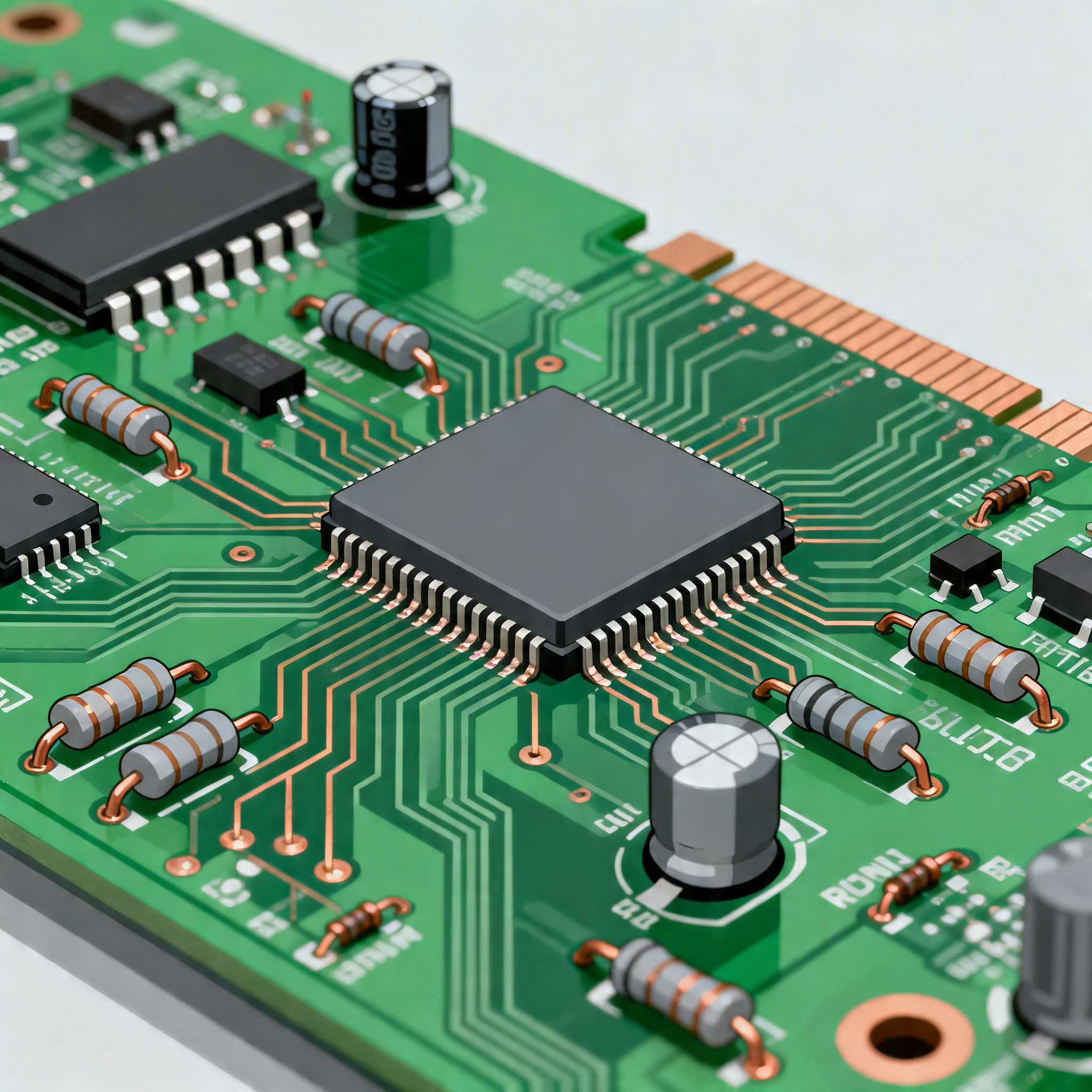
PCBs are the foundation of electronic devices, providing the physical platform for mounting and interconnecting various components like resistors, capacitors, and IC chips. The architecture of a PCB involves multiple layers, each serving a specific function, such as signal routing, power distribution, or grounding. The design principles for PCBs are guided by standards like IPC-A-610 and IPC-2221, which ensure reliability and quality in manufacturing. When it comes to low-volume orders, the choice of components, particularly IC chips, plays a significant role in determining the overall cost and performance of the PCB. Factors such as CPU speed, memory capacity, and peripheral interfaces are critical in selecting the right ICs for your application. Understanding these core concepts is essential for optimizing both the design and cost of your PCB prototypes.
Detailed Specifications
When selecting IC chips for your PCB, it's important to consider various specifications that impact the device's performance and cost. Key specifications include CPU speed, memory capacity, available peripherals, power consumption, and packaging type. These factors not only influence the technical capabilities of the PCB but also its manufacturing complexity and cost.
```html
| Specification | Details | Impact |
| CPU Speed | 1.2 GHz | Higher speed for faster processing |
| Memory | 512 MB RAM | More memory for complex tasks |
| Peripherals | USB, I2C, SPI | Versatile connectivity options |
| Power Consumption | 3.3V, 500mA | Efficiency in power usage |
| Package Type | LQFP | Compact form factor |
| Operating Temperature | -40°C to 85°C | Wide range for various environments |
| Storage Capacity | 32 GB | Increased data storage |
| Clock Frequency | 100 MHz | Timing accuracy |
| Pin Count | 64 pins | More connections for flexibility |
| Voltage Range | 1.8V to 5V | Compatibility with different systems |
```
Key Takeaways from the Specifications
The specifications outlined in the table are fundamental in determining the performance and suitability of an IC chip for your PCB design. A higher CPU speed, for instance, allows for faster data processing, which is crucial for applications requiring real-time data handling. Similarly, having a broad range of peripherals like USB and I2C enhances the connectivity and versatility of the PCB, enabling it to interface with various external devices. Power consumption is another critical factor, as efficient power usage extends the battery life in portable applications. Understanding these specifications helps in selecting the right components that align with your design goals and budget constraints.
```html
| Parameter | Typical Value | Explanation |
| Operating Voltage | 3.3V | Standard voltage for most ICs |
| Max Current | 500mA | Maximum current draw |
| Timing Parameters | 10ns | Signal propagation delay |
| Input/Output Voltage | 0V to 3.3V | Voltage levels for I/O |
| Power Dissipation | 1.5W | Heat generated during operation |
| Input Leakage Current | 1uA | Leakage current into the input pins |
| Output Drive Current | 20mA | Current that can be driven by an output pin |
| ESD Protection | 2kV | Electrostatic discharge protection level |
| Clock Skew | 5ps | Difference in arrival time of clock signals |
| Thermal Resistance | 50°C/W | Heat dissipation efficiency |
| Short Circuit Current | 50mA | Current in the event of a short circuit |
| Signal Rise/Fall Time | 5ns | Time for signal to transition between high and low |
```
Practical Implications
The electrical characteristics of an IC chip are pivotal in determining its operational efficiency and reliability. Operating voltage and current specifications, for instance, indicate the power requirements and limits of the chip, which are essential for ensuring compatibility with the power supply design of the PCB. Timing parameters, such as signal propagation delay, play a critical role in defining the speed at which data can be processed and transferred within the system. Similarly, ESD protection levels are crucial for safeguarding the IC against damage from electrostatic discharge, thereby enhancing the durability of the device. By carefully analyzing these characteristics, engineers can make informed decisions that balance performance and reliability in their PCB designs.
```html
| Application | Configuration | Benefits |
| Consumer Electronics | Embedded MCU | Cost-effective, compact design |
| Industrial Automation | High-speed DSP | Real-time processing capability |
| Automotive Systems | Robust ICs | Enhanced reliability and safety |
| Medical Devices | Low-power ASIC | Extended battery life |
| Telecommunications | High-frequency RF | Improved signal integrity |
| IoT Devices | Wireless SoC | Integrated connectivity features |
| Wearable Tech | Ultra-low power ICs | Prolonged usage without frequent charging |
| Data Centers | Multi-core processors | High computational power |
```
Application Guidelines
The application comparison table highlights various use cases for different IC configurations, emphasizing the versatility and adaptability of these components in diverse fields. For instance, in consumer electronics, embedded MCUs offer a compact and cost-effective solution, ideal for mass-market products. In contrast, industrial automation demands high-speed digital signal processors (DSPs) capable of real-time data processing to maintain system efficiency and productivity. Automotive systems prioritize robust ICs to ensure safety and reliability under harsh conditions. By understanding the specific requirements and benefits of each application, engineers can tailor their component selection to achieve optimal performance, efficiency, and cost-effectiveness in their PCB designs.
Design Considerations
Designing a PCB involves several critical considerations that impact both the functionality and manufacturability of the final product. One of the primary factors is the choice of materials, which affects the thermal and electrical properties of the PCB. High-frequency applications, for example, require substrates with low dielectric loss to minimize signal attenuation. Another key consideration is the layer stack-up, which determines the routing complexity and electromagnetic compatibility of the board. Designers must also account for trace width and spacing to ensure proper current carrying capacity and minimize the risk of short circuits. Additionally, component placement and routing are crucial for optimizing signal integrity and minimizing electromagnetic interference. By adhering to industry standards and best practices, engineers can create PCB designs that meet performance requirements while ensuring cost-effective manufacturability.
Step-by-Step Implementation
Creating a PCB prototype involves a series of detailed steps, each requiring careful attention to ensure the desired outcome:
1. **Define Requirements:** Begin by clearly outlining the functional and performance requirements of the PCB, including size, power consumption, and connectivity needs.
2. **Select Components:** Based on the defined requirements, choose suitable components, particularly ICs, ensuring they meet the necessary specifications and availability.
3. **Schematic Design:** Develop the circuit schematic, ensuring all connections are accurately represented and that the design adheres to industry standards.
4. **PCB Layout:** Translate the schematic into a physical layout, considering factors such as trace routing, component placement, and thermal management.
5. **Design Verification:** Use simulation tools to verify the electrical performance and signal integrity of the PCB design, making adjustments as needed.
6. **Prototype Fabrication:** Send the final design files to a PCB manufacturer to create a physical prototype, specifying any unique requirements or constraints.
7. **Assembly and Testing:** Assemble the prototype by soldering components onto the board, followed by thorough testing to validate functionality and performance.
8. **Iterate and Refine:** Based on test results, make any necessary design modifications and repeat the prototyping process to achieve the desired outcome.
Common Issues & Solutions
PCB prototyping can present several challenges, but with the right approach, these issues can be effectively addressed:
1. **Signal Integrity Problems:** Use proper grounding and shielding techniques to minimize interference and ensure clean signal transmission.
2. **Thermal Management:** Implement adequate heat dissipation methods, such as thermal vias and heat sinks, to prevent overheating and ensure reliable operation.
3. **Component Availability:** Plan for potential supply chain disruptions by identifying alternative components that meet the same specifications.
4. **Manufacturing Tolerances:** Work closely with manufacturers to understand their capabilities and constraints, ensuring the design aligns with their processes.
5. **Cost Overruns:** Optimize the design for cost efficiency by selecting cost-effective components and minimizing unnecessary complexity.
Applications & Use Cases
PCBs are integral to a wide range of applications, each with unique requirements and challenges. In consumer electronics, PCBs enable the miniaturization and integration of complex functions into compact devices. In industrial automation, they provide the backbone for robust and reliable control systems. Automotive applications demand PCBs that can withstand extreme temperatures and vibrations while maintaining safety and performance. In the medical field, PCBs are used in life-saving equipment where precision and reliability are paramount. Telecommunications rely on PCBs for high-speed data processing and transmission, while IoT devices require efficient and low-power designs to support connectivity and smart functionalities. By understanding these diverse applications, engineers can tailor their designs to meet specific industry needs.
Selection & Sourcing Guide
Selecting the right ICs for your PCB design involves evaluating specifications, availability, and cost. A useful resource for sourcing components is [IC Online](https://www.ic-online.com/), which provides a comprehensive database of available ICs, complete with datasheets and pricing information. This platform allows engineers to compare different options, ensuring they select components that meet their design requirements and budget constraints.
FAQ
1. **What are the key factors affecting PCB prototype costs?**
- Material selection, component choice, design complexity, and manufacturing processes all influence the cost.
2. **How can I ensure my PCB design meets industry standards?**
- Adhering to IPC standards and collaborating with experienced manufacturers ensures compliance and quality.
3. **What is the typical lead time for low-volume PCB orders?**
- It varies, but quick-turn services like Nova PCBA offer turnaround times as short as a few days.
4. **How do I choose the right IC for my application?**
- Evaluate the specifications, datasheet, and real-world application needs to select the most suitable IC.
5. **What are common pitfalls in PCB prototyping?**
- Overlooking signal integrity, thermal management, and manufacturing constraints can lead to issues.
6. **How can I reduce the cost of my PCB design?**
- Optimize the design for manufacturability, select cost-effective components, and minimize unnecessary complexity.
7. **What role do IC datasheets play in the selection process?**
- Datasheets provide critical information on specifications, performance, and compatibility, guiding the selection.
8. **How important is component placement in PCB design?**
- Proper placement is crucial for maintaining signal integrity, minimizing interference, and ensuring efficient layout.
9. **What tools are available for PCB design verification?**
- Simulation and analysis tools such as SPICE and electromagnetic field solvers help verify design performance.
10. **Why is thermal management important in PCB design?**
- Effective thermal management prevents overheating, ensuring reliability and longevity of the PCB.
Conclusion
Understanding the intricacies of PCB prototype costs, especially for low-volume orders, is essential for optimizing design and manufacturing processes. By carefully considering component specifications, electrical characteristics, and application requirements, engineers can create efficient, reliable, and cost-effective PCB designs. Utilizing resources like IC Online for component selection and adhering to industry standards ensures quality and performance, paving the way for successful product development in today's competitive electronics landscape.