Avoiding PCBA Manufacturing Defects: Best Practices for 2026 and Beyond
Avoiding PCBA Manufacturing Defects: Best Practices for 2026 and Beyond Introduction In the rapidly evolving world of electronics, avoiding printed circuit board assembly (PCBA) manufacturing defects ...
Introduction
In the rapidly evolving world of electronics, avoiding printed circuit board assembly (PCBA) manufacturing defects is crucial for maintaining product quality and reliability. As we approach 2026, the complexity of electronic devices continues to increase, making it imperative for engineers to adopt best practices in component selection, design, and manufacturing. This article focuses on integrated circuit (IC) chips, examining their specifications, datasheets, and application circuits to provide a comprehensive guide for reducing defects in PCBA manufacturing.
Technical Overview
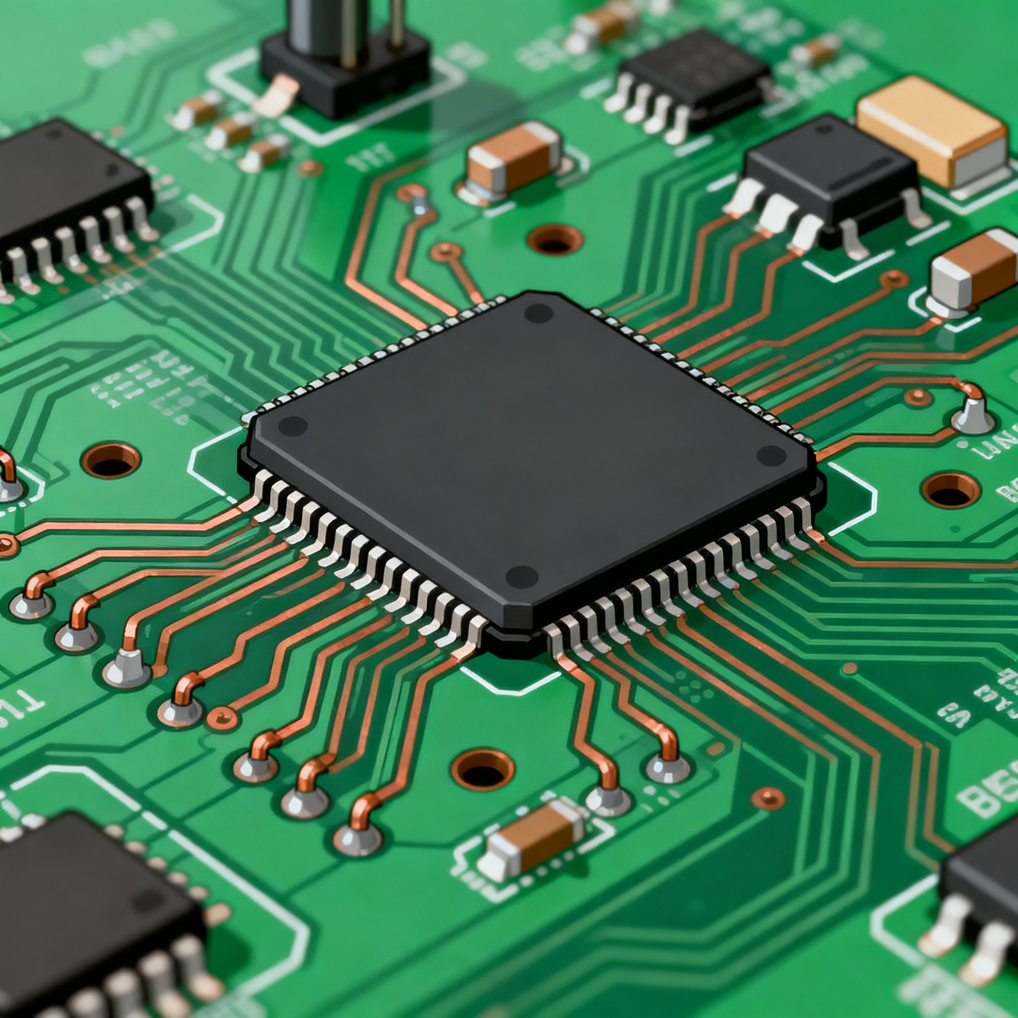
Integrated circuits (ICs) are the building blocks of modern electronic systems, providing essential functionalities such as processing, memory storage, and signal management. IC chips come in various forms, including microcontrollers, digital signal processors (DSPs), and application-specific integrated circuits (ASICs). Each type of IC chip has its own architecture and principles, which influence its performance and suitability for different applications.
The architecture of an IC chip typically includes a central processing unit (CPU), memory units, input/output (I/O) ports, and peripheral interfaces. The choice of architecture depends on the intended application, with considerations for processing power, memory capacity, and connectivity options. Additionally, the principles of power management, thermal performance, and signal integrity play a critical role in ensuring the reliability and efficiency of IC chips in PCBA manufacturing.
Detailed Specifications
When selecting IC chips for PCBA manufacturing, it is essential to consider their core specifications. These specifications include CPU speed, memory capacity, peripheral interfaces, power requirements, and package types. Understanding these specifications helps engineers choose the right components for their designs, ensuring optimal performance and compatibility with other system elements.
| Specification | Details | Significance |
|---|---|---|
| CPU Speed | 1.2 GHz | Determines processing power |
| Memory | 512 MB RAM, 4 GB Flash | Storage for data and programs |
| Peripherals | USB, SPI, I2C, UART | Connectivity options |
| Power Supply | 3.3V, 5V | Voltage levels for operation |
| Package Type | LQFP, BGA | Physical form factor |
| Temperature Range | -40°C to 85°C | Operational environment |
| Clock Frequency | 100 MHz | Determines timing precision |
| ADC/DAC | 12-bit resolution | Analog signal processing |
| GPIO Pins | 40 | General-purpose I/O |
| Power Consumption | 300 mW | Energy efficiency |
| Security Features | Encryption, Secure Boot | Data protection |
Key Takeaways from the Specifications
The core specifications of IC chips provide valuable insights into their capabilities and compatibility with different applications. A high CPU speed indicates robust processing power, essential for demanding computational tasks. Memory specifications, including RAM and Flash, determine the storage capacity for data and programs, influencing the chip's performance in data-intensive applications.
Peripheral interfaces such as USB, SPI, and I2C offer various connectivity options, enabling seamless integration with other components. Power supply requirements and package types are crucial for ensuring compatibility with the overall system design. Moreover, temperature range and power consumption are vital considerations for applications operating in diverse environmental conditions.
| Characteristic | Value | Impact |
|---|---|---|
| Operating Voltage | 1.8V to 3.6V | Determines power compatibility |
| Max Current | 500 mA | Current handling capacity |
| Input Voltage High | 2.0V min | Logic level threshold |
| Input Voltage Low | 0.8V max | Logic level threshold |
| Output Voltage High | 2.4V min | Output signal strength |
| Output Voltage Low | 0.4V max | Output signal strength |
| Propagation Delay | 10 ns | Signal processing time |
| Rise/Fall Time | 5 ns | Signal transition speed |
| Input Capacitance | 5 pF | Load on input signal |
| Output Capacitance | 7 pF | Load on output signal |
| ESD Protection | 2 kV | Electrostatic discharge resilience |
Practical Implications
The electrical characteristics of IC chips are critical for ensuring their reliable operation within electronic systems. Operating voltage ranges and maximum current ratings define the power compatibility of the chip with the system. Input and output voltage levels determine the logic thresholds, which are crucial for signal integrity and communication between components.
Propagation delay and rise/fall times are essential for understanding the timing precision and signal transition speeds, impacting the overall performance of the IC chip. Input and output capacitances affect the load on signals, influencing the speed and stability of data transmission. ESD protection is vital for safeguarding the chip against electrostatic discharge, a common cause of component failure in PCBA manufacturing.
| Application | Configuration | Benefits |
|---|---|---|
| Consumer Electronics | High-speed CPU, ample memory | Enhanced user experience |
| Automotive Systems | Robust power management, ESD protection | Reliability in harsh environments |
| Industrial Automation | Multiple I/O interfaces, real-time processing | Efficient control and monitoring |
| Medical Devices | Low power consumption, high precision | Extended battery life, accuracy |
| Telecommunications | High-speed data processing, secure communication | Fast and secure connectivity |
| IoT Devices | Integrated peripherals, low power | Seamless connectivity, energy efficiency |
| Wearable Technology | Compact package, low power | Portability, extended usage |
Application Guidelines
The application comparison table highlights the diverse use cases and configurations of IC chips across various industries. In consumer electronics, high-speed CPUs and ample memory are crucial for delivering an enhanced user experience, while automotive systems prioritize robust power management and ESD protection to ensure reliability in harsh environments.
Industrial automation demands multiple I/O interfaces and real-time processing capabilities for efficient control and monitoring. Medical devices benefit from low power consumption and high precision for extended battery life and accuracy. Telecommunications applications require high-speed data processing and secure communication for fast and reliable connectivity. IoT devices and wearable technology emphasize integrated peripherals and low power consumption for seamless connectivity and portability.
Design Considerations
When designing PCBA systems, several key considerations must be taken into account to avoid manufacturing defects. First, component selection is critical. Engineers must ensure that the selected IC chips meet the necessary specifications and are compatible with other components in the system. This includes verifying datasheet information and consulting with manufacturers to avoid potential mismatches.
Second, layout design plays a significant role in minimizing defects. Proper routing of traces, maintaining adequate spacing between components, and adhering to design rules are essential for preventing short circuits and signal interference. Utilizing design software with built-in rule checks can help automate this process and reduce human error.
Third, thermal management is crucial for maintaining the performance and longevity of IC chips. Implementing appropriate heat sinks, thermal vias, and airflow considerations can prevent overheating and ensure stable operation. Additionally, power management strategies, such as using decoupling capacitors and voltage regulators, help maintain a stable power supply to the IC chips.
Finally, thorough testing and inspection are vital for identifying and rectifying defects before mass production. Employing techniques such as automated optical inspection (AOI) and in-circuit testing (ICT) can help detect soldering issues, component misalignments, and other defects early in the manufacturing process.
Step-by-Step Implementation
- Component Selection: Begin by identifying the key specifications required for your application. Consult datasheets and manufacturer resources to ensure compatibility with other system components.
- Design Layout: Use PCB design software to create a layout that adheres to design rules and standards. Pay attention to trace routing, component spacing, and signal integrity.
- Simulation: Perform simulations to validate the design and identify potential issues. Use tools to analyze signal integrity, thermal performance, and power distribution.
- Prototype Development: Develop a prototype of the design for testing. This allows for real-world validation and identification of any unforeseen issues.
- Testing and Inspection: Conduct thorough testing using AOI, ICT, and other inspection techniques to identify defects. Address any issues before moving to mass production.
- Manufacturing: Collaborate with a reputable PCBA manufacturer that adheres to industry standards and best practices. Ensure the manufacturer understands the design requirements and specifications.
- Quality Assurance: Implement quality assurance processes to monitor production quality. Use statistical process control and other techniques to maintain consistency.
- Continuous Improvement: Gather feedback from testing and production to refine the design and manufacturing processes. Implement changes to improve efficiency and reduce defects in future iterations.
Common Issues & Solutions
- Soldering Defects: Use appropriate soldering techniques and materials. Implement inspection processes to identify and correct defects early.
- Component Misalignment: Ensure accurate placement during assembly using automated equipment and alignment tools.
- Signal Integrity Issues: Optimize trace routing and ensure adequate grounding to prevent interference and signal degradation.
- Overheating: Implement thermal management solutions such as heat sinks and airflow considerations to prevent overheating.
- Power Supply Instability: Use decoupling capacitors and voltage regulators to maintain a stable power supply to the IC chips.
- ESD Damage: Implement ESD protection measures, such as grounding and shielding, to prevent damage from electrostatic discharge.
Applications & Use Cases
IC chips are integral to a wide range of applications across various industries. In consumer electronics, they power devices such as smartphones, tablets, and laptops, providing processing capabilities and connectivity options. Automotive systems rely on IC chips for engine control, infotainment systems, and advanced driver-assistance systems (ADAS), ensuring safety and performance.
Industrial automation utilizes IC chips for process control, monitoring, and communication, enhancing efficiency and productivity. In the medical field, IC chips enable the development of portable and precise diagnostic devices, improving patient care. Telecommunications applications benefit from high-speed data processing and secure communication, supporting the growing demand for fast and reliable connectivity.
Selection & Sourcing Guide
When selecting and sourcing IC chips for your projects, it is essential to consult reliable resources and suppliers. Websites like IC Online provide comprehensive databases of IC chips, including specifications, datasheets, and availability. Collaborating with reputable suppliers and manufacturers ensures that you receive high-quality components that meet your design requirements.
FAQ
- What are the key specifications to consider when selecting an IC chip? Core specifications such as CPU speed, memory capacity, peripheral interfaces, and power requirements are essential considerations.
- How can I ensure compatibility between IC chips and other components? Consult datasheets and manufacturer resources to verify compatibility and avoid potential mismatches.
- What are some common PCBA manufacturing defects? Common defects include soldering issues, component misalignment, and signal integrity problems.
- How can I prevent overheating in IC chips? Implement thermal management solutions such as heat sinks and airflow considerations.
- What testing methods can be used to identify defects in PCBA manufacturing? Automated optical inspection (AOI) and in-circuit testing (ICT) are effective methods for identifying defects.
- What is the significance of ESD protection in IC chips? ESD protection safeguards the chip against electrostatic discharge, preventing damage and ensuring reliability.
- How can I improve the efficiency of my PCBA manufacturing process? Implement quality assurance processes, gather feedback, and continuously refine design and manufacturing processes.
- What resources are available for sourcing IC chips? Websites like IC Online provide comprehensive databases of IC chips and suppliers.
- How can I ensure signal integrity in my PCBA design? Optimize trace routing, maintain adequate grounding, and use simulation tools to analyze signal integrity.
- What are the benefits of collaborating with a reputable PCBA manufacturer? Reputable manufacturers adhere to industry standards and best practices, ensuring high-quality production and reduced defects.
Conclusion
Avoiding PCBA manufacturing defects requires a comprehensive understanding of IC chip specifications, design considerations, and manufacturing processes. By focusing on component selection, layout design, thermal management, and thorough testing, engineers can minimize defects and ensure high-quality, reliable electronic products. As the electronics industry continues to evolve, adopting these best practices will be essential for success in 2026 and beyond.