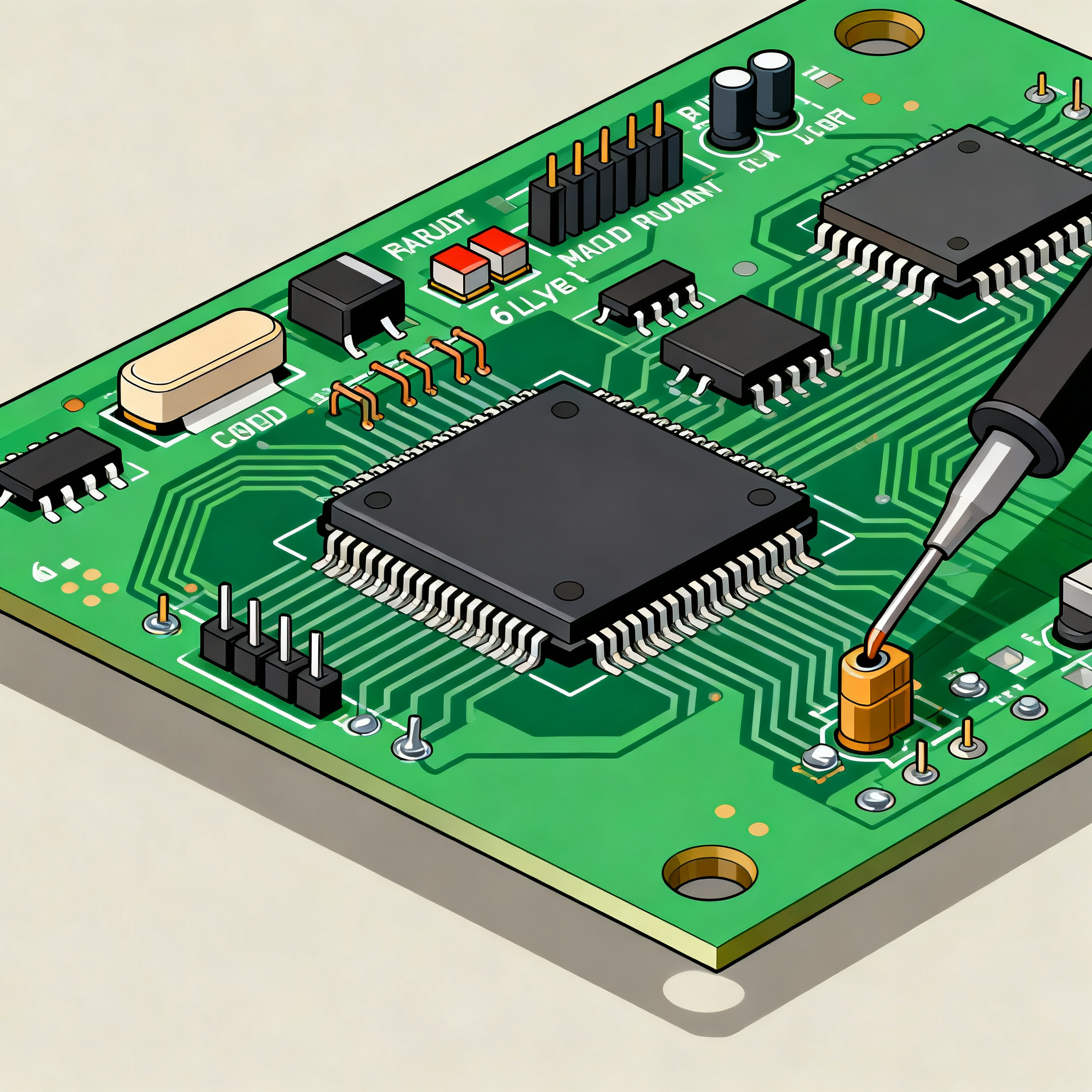
Avoiding Common SMT Soldering Defects in 6-Layer Electronic PCB Assembly
Avoiding Common SMT Soldering Defects in 6-Layer Electronic PCB Assembly When Solder Joints Fail on Dense 6-Layer Assemblies You’ve just pulled the first panel from reflow. Under the microscope, a 0.4...
Avoiding Common SMT Soldering Defects in 6-Layer Electronic PCB Assembly
When Solder Joints Fail on Dense 6-Layer Assemblies
You’ve just pulled the first panel from reflow. Under the microscope, a 0.4 mm-pitch QFN shows a telltale hairline gap between pad and lead — an open circuit. On the same board, a 0201 capacitor stands upright like a tombstone, its opposite pad untouched by solder. The root cause isn’t a single rogue variable; it’s the interplay of paste deposition, thermal mass, and design choices that 6‑layer boards magnify.
Open circuits or insufficient solder often begin at the printer. Aivon’s analysis of common SMT defects confirms that “open circuits or insufficient solder result when too little paste is deposited, leaving pads without adequate material for a reliable joint.” Clogged stencil apertures, uneven squeegee pressure, or paste slump can starve a joint before the board ever sees heat. On a 6‑layer board with dense inner planes, that marginal paste deposit then faces a thermal environment that pulls heat away unevenly, turning a small printing flaw into a field failure.
The stakes have risen as designs pack more functionality into smaller footprints. Altium’s process engineers note that “as more designs are using smaller components with surface‑mount pads, SMT soldering defects can mount and impact yields due to various design and manufacturing problems.” Problems that were once minor — a degree of tombstoning on 0805 passives, a few voids in a BGA — now cascade into rework costs that erode margins on medium‑volume runs. When you add lead‑free alloys with their higher surface tension and narrower process windows, the margin for error shrinks further.
Six‑layer assemblies sit at the intersection of these trends. They offer the signal integrity and EMI control that modern electronics demand, but their multiple power and ground planes create thermal and mechanical conditions that punish process drift. For the engineer releasing a design and the buyer qualifying a supplier, understanding why these defects cluster on 6‑layer boards — and how to prevent them — isn’t optional. It’s the difference between a predictable NPI ramp and a line stoppage.
Why 6-Layer Boards Amplify SMT Soldering Defects
A 6‑layer stackup typically dedicates two internal layers to power and ground planes. Those solid copper pours act as heat sinks during reflow, slowing the ramp rate at component pads while the surrounding laminate heats faster. The result is a thermal gradient across the board that drives several defect mechanisms into overdrive.
PCBCart’s defect guide underscores that “high‑quality, reliable SMT assembly can be achieved by integrating robust DFM principles with accurate process control throughout — from verification of solder paste volume through SPI to reflow thermal profile optimization for balanced heating and optimal TAL.” On a 6‑layer board, that balanced heating is harder to achieve. The large thermal mass of inner planes demands a longer soak zone to equalize temperatures, and if the profile isn’t tuned to the specific stackup, tombstoning of small passives and voiding in BGAs become common.
Asymmetric copper distribution adds another layer of risk. When one side of a board has significantly more copper than the other — a frequent scenario in mixed‑signal 6‑layer designs — the board warps during reflow, lifting pads out of coplanarity with component leads. Lead‑free solders exacerbate the problem. Altium’s soldering defect analysis points out that “lead‑free solders on a BGA may require a larger standoff distance due to their higher surface tension, and the standoff/temperature profile should be checked with a test coupon prior to full‑scale manufacturing.” If the profile doesn’t accommodate that larger standoff, you’ll see head‑in‑pillow defects or intermittent opens that only appear after thermal cycling.
The table below maps how defect susceptibility shifts as layer count and plane configuration change. Use it to anticipate which failure modes deserve the most attention during DFM and process setup.
| Defect Mechanism | 2‑Layer | 4‑Layer | 6‑Layer | 8‑Layer | Root Cause & Notes |
|---|---|---|---|---|---|
| Tombstoning | Low | Medium | High | Very High | Uneven heating across pads due to inner plane heat sinking; worse with small passives (0201/0402) and lead‑free solder. |
| Bridging | Low | Medium | Medium‑High | High | Fine‑pitch components on dense 6‑layer boards increase short risk; paste slump and stencil design are critical. |
| Voiding (BGA/QFN) | Low | Medium | High | High | Outgassing trapped by large thermal mass; requires optimized soak and peak TAL. |
| Warpage‑Induced Opens | Low | Medium | Medium‑High | High | Asymmetric copper distribution across layers; lead‑free reflow temperatures amplify CTE mismatch. |
| Insufficient Solder / Opens | Low | Medium | Medium | Medium‑High | Via‑in‑pad wicking, stencil clogging, and paste volume asymmetry; more layers increase via density. |
| Head‑in‑Pillow (BGA) | Rare | Low | Medium | Medium‑High | Lead‑free alloy surface tension and warpage; larger standoff needed, verified by test coupon. |
Key takeaway: The jump from 4 to 6 layers isn’t just two extra copper sheets — it’s a shift in thermal behavior that demands deliberate process tuning. If your current reflow recipe was developed on a 4‑layer test vehicle, expect to re‑qualify it when moving to a 6‑layer design with heavy ground planes.
How 6-Layer Stackups Compare to 2- and 8-Layer Designs in SMT Yield
Choosing the right layer count is a trade‑off between electrical performance, cost, and assembly robustness. A 2‑layer board is simple and cheap, but offers no dedicated power/ground planes, forcing you to route supply traces that compromise EMI and signal integrity. An 8‑layer board gives you ample shielding and routing space, but the added thermal mass and cost can be overkill for many applications. Six‑layer designs hit a sweet spot, but that sweet spot comes with specific assembly challenges.
JLCPCB’s multilayer comparison notes that “2‑6 layer boards are the most economical and fastest to produce (typically 3‑5 days lead time)” and that “6‑layer PCBs strike an optimal balance: they add dedicated ground/power planes for better EMI control and signal integrity.” That balance, however, introduces the thermal and warpage risks we’ve discussed. The table below puts numbers and qualitative assessments around the trade‑offs, helping you decide when the extra layers are worth the assembly risk.
| Comparison Metric | 2‑Layer PCB | 6‑Layer PCB | 8‑Layer PCB | Selection Criteria & Failure Boundary |
|---|---|---|---|---|
| Typical SMT First‑Pass Yield (with DFM) | 98–99% | 95–98% | 93–97% | Yield drops as thermal mass and warpage increase; 6‑layer can match 2‑layer with optimized profiling. |
| Defect Susceptibility | Low | Medium | High | Bridging, tombstoning, and voiding rise with layer count; 6‑layer is a threshold where process control becomes critical. |
| Thermal Management Challenge | Minimal | Moderate | Significant | Inner planes demand longer soak and controlled ramp; 6‑layer requires thermocouple profiling on actual board. |
| EMI Control | Poor | Good | Excellent | 6‑layer provides dedicated planes for return paths; 2‑layer struggles above 50 MHz. |
| Relative Cost (1k units, FR‑4) | 1× (baseline) | 2.5–3.5× | 4–6× | 6‑layer cost is justified when signal integrity or density demands it; 8‑layer only for very high‑speed or HDI needs. |
| Prototype Lead Time | 2–4 days | 3–5 days | 5–8 days | Fast‑turn 6‑layer services exist; verify that the supplier’s quick‑turn process doesn’t skip DFM checks. |
| Warpage Risk | Low | Medium | High | Asymmetric copper on 6‑layer can cause bow & twist; specify copper balance and consider symmetrical stackup. |
For many IoT gateways, industrial controllers, and automotive infotainment modules, 6‑layer is the pragmatic choice — but only if you treat the assembly process as an extension of the design. A 2‑layer board might forgive a sloppy reflow profile; a 6‑layer board won’t. If your design can achieve acceptable EMI and routing density on 4 layers, you might avoid the added thermal headaches altogether. But when you need the extra planes, the comparison shows that the yield penalty is manageable with the right process controls.
Design and Process Tweaks That Prevent SMT Defects on 6-Layer PCBs
Preventing defects on 6‑layer assemblies starts at the CAD station and continues through every step of SMT production. The following practices address the most common root causes, from land pattern geometry to reflow profiling.
DFM and Land Pattern Discipline
E‑Micrologix’s defect prevention guide advises to “follow IPC‑7351 land pattern standards for two‑terminal components” and to “verify paste volume symmetry through solder paste inspection after printing.” On a 6‑layer board, symmetrical pad geometry is non‑negotiable. Even a slight imbalance in pad size or thermal connection to inner planes can cause one end of a chip component to reflow before the other, triggering tombstoning. Ensure that both pads of a two‑terminal device see the same copper connection to inner layers — avoid tying one pad to a large ground plane while the other connects only to a thin trace.
Stencil Design and Paste Deposition
Insufficient solder remains a leading cause of opens. Aivon’s troubleshooting guide highlights that clogged stencil apertures and uneven squeegee pressure are frequent culprits. For 6‑layer boards with fine‑pitch components, use electroformed or laser‑cut stencils with nano‑coating to improve paste release. Set aperture area ratio ≥0.66 for 0.4 mm‑pitch QFNs, and specify stencil thickness between 0.1 mm and 0.125 mm depending on the mix of fine‑pitch and larger power devices. Clean stencils every 5–10 prints to prevent aperture clogging, and monitor squeegee pressure with automated feedback if available.
Placement Accuracy and Coplanarity
PCBSync’s solder joint defect reference recommends to “fix by checking coplanarity, flattening warpage with a tuned profile, and verifying placement; on gull‑wing leads a heel fillet must be present.” On a 6‑layer board, warpage can lift QFP leads off their pads by tens of microns — enough to prevent fillet formation. Verify placement accuracy within ±0.05 mm and use a placement machine with vision alignment. After reflow, inspect gull‑wing leads for heel fillets; their absence often points to coplanarity issues or insufficient paste volume.
Reflow Profiling and TAL Optimization
PCBCart’s process guidance stresses the importance of “optimizing TAL to avoid bridging and tombstoning.” For a 6‑layer board with heavy inner planes, a profile that works on a 4‑layer test coupon may leave cold spots. Use a real board instrumented with thermocouples at the largest BGA, the smallest passive, and near any large copper pours. Aim for a soak zone of 60–120 seconds at 150–180 °C to equalize temperatures, then ramp to peak at 2–3 °C/s. Keep time above liquidus (TAL) within 60–90 seconds for lead‑free SAC305, and verify that all joints reach a minimum peak temperature of 235 °C. For mixed‑technology boards, consider a nitrogen atmosphere to reduce oxidation and improve wetting on lead‑free alloys.
Process Parameters at a Glance
| Process Step | Parameter | Recommended Value for 6‑Layer | Verification Method |
|---|---|---|---|
| Stencil Design | Aperture area ratio | ≥0.66 (0.4 mm pitch); ≥0.75 for 0201 | SPI after first print |
| Stencil Thickness | Thickness | 0.100–0.125 mm | Micrometer on stencil foil |
| Solder Paste Inspection | Volume tolerance | ±30% of nominal for chip components; ±20% for fine‑pitch | 3D SPI system, 100% inspection |
| Placement | Accuracy | ±0.05 mm (3σ) | First‑article vision check |
| Reflow Soak | Soak temperature & time | 150–180 °C, 60–120 s | Thermocouple on actual board |
| Reflow Ramp Rate | Ramp to peak | 2–3 °C/s | Profile graph analysis |
| Peak Temperature (SAC305) | Peak range | 235–245 °C | Thermocouple at coldest joint |
| Time Above Liquidus (TAL) | TAL | 60–90 s | Profile graph analysis |
| Stencil Cleaning | Frequency | Every 5–10 prints | Automated under‑stencil wipe |
Tip: Before releasing a 6‑layer design to fabrication, run a free DFM review. PCBSync’s service offers “free DFM review and instant pricing — no minimums, fast turnaround.” Many assemblers, including NovaPCBA, provide similar checks that catch via‑in‑pad wicking, insufficient annular rings, and copper imbalance before they become rework drivers.
Questions Engineers and Buyers Ask About 6-Layer SMT Assembly
Q: Does a 6-layer board always have higher SMT defect rates than a 4-layer board?
Not necessarily. Defect rates depend more on stackup symmetry, copper balance, and process control than on layer count alone. However, 6‑layer boards often introduce larger ground/power planes that increase thermal mass, making them more sensitive to reflow profile tuning. With proper DFM and profiling, yields can match or exceed simpler designs.
Q: What is the most common soldering defect when mixing heavy ground planes with fine-pitch components on a 6-layer board?
Tombstoning of small passives and bridging on fine‑pitch ICs are most frequent. The heavy inner planes draw heat away from pads unevenly, causing one end of a component to reflow before the other, while solder paste slump on tightly spaced leads leads to shorts. Symmetrical pad design and controlled preheat soak mitigate both.
Q: How do I specify a reflow profile that prevents tombstoning on 6-layer boards with unbalanced copper?
Focus on a longer soak zone to equalize temperatures across the board, and limit the peak reflow ramp rate to 2–3 °C/s. Use thermocouple profiling on the actual board to identify cold spots near large copper pours, and adjust conveyor speed accordingly. Verify with a test coupon that includes the critical component mix.
Q: What DFM checks are critical before releasing a 6-layer design to assembly?
Verify pad geometry against IPC‑7351, ensure symmetrical paste stencil apertures for two‑terminal components, check via‑in‑pad plugging to avoid wicking, confirm copper balance on each layer to minimize warpage, and run a solder paste inspection (SPI) window on the first article. A free DFM review from the assembler can catch many of these before fabrication.
Q: How does lead-free solder affect defect rates on 6-layer PCBs compared to leaded solder?
Lead‑free alloys have higher surface tension and melt temperatures, which increase the risk of tombstoning, voiding, and poor hole fill on 6‑layer boards with large thermal mass. They also demand tighter reflow windows and may require larger BGA standoff heights. Process adjustments — like nitrogen reflow and optimized preheat — help, but lead‑free always requires more rigorous profiling than SnPb.
References & Further Reading
- Common SMT PCB Assembly Defects — Aivon
- Common PCB Defects: Causes, Solutions, and Prevention — e-Micrologix
- Common SMT Defects to Avoid During Soldering — Altium
- Common SMT Defects and How to Avoid Them — PCBCart
- Comparing 6‑Layer PCBs with Other Multilayer PCBs — JLCPCB
- Solder Joint Defects: 25 Common SMT Defects, Causes & Fixes — PCBSync
- The Printed Circuit Assembler’s Guide to...Solder Defects — I‑Connect007
- IPC‑7351 Land Pattern Standard
At NovaPCBA, we specialize in high‑yield 6‑layer SMT assembly, combining rigorous DFM reviews, 3D SPI, and profile optimization tailored to your stackup. Explore our PCB assembly services to see how we help engineers and buyers eliminate soldering defects before they reach the production floor.