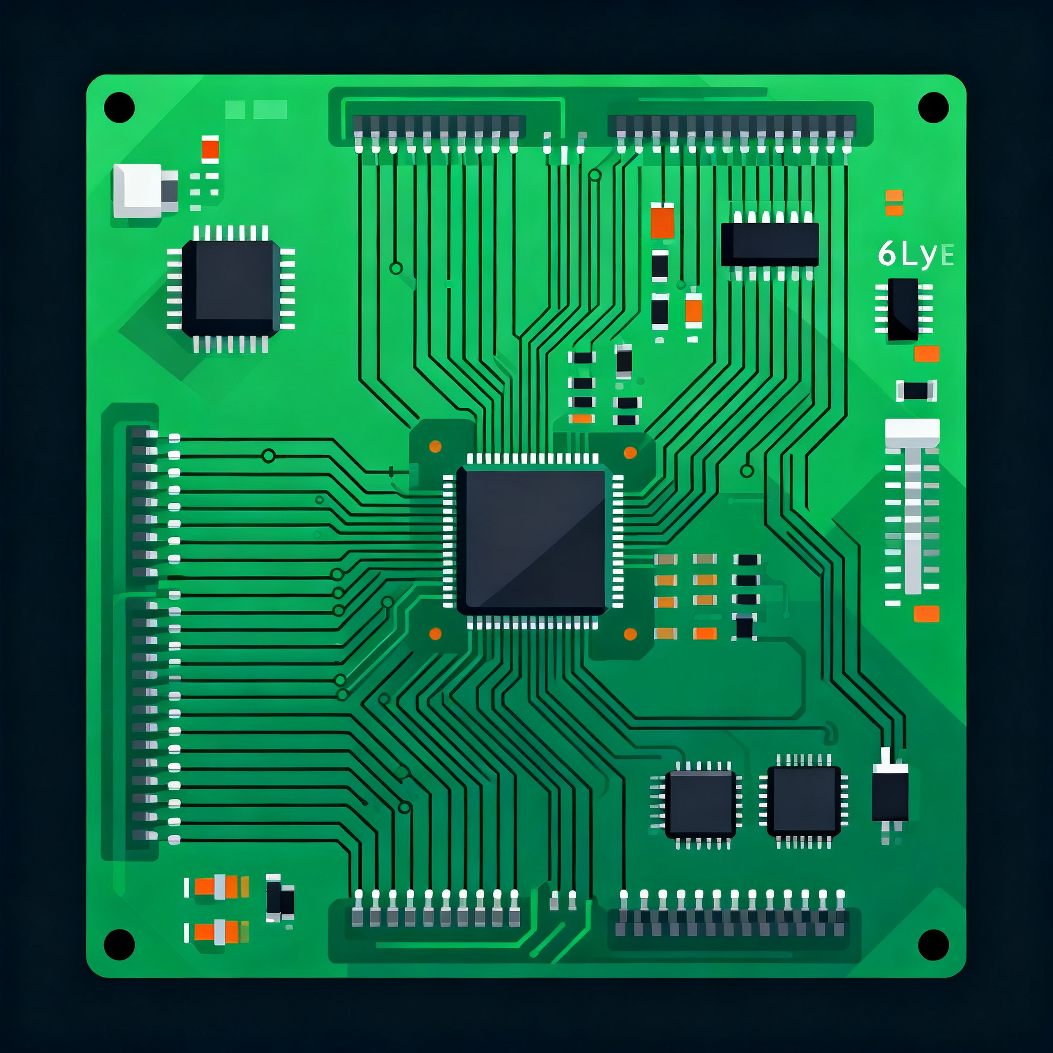
Avoid These 7 Costly PCB Layout Design Rule Pitfalls in 6-Layer Boards
Why a ‘DRC-Pass’ Doesn’t Guarantee a Cost-Free 6-Layer Board Design rule checks (DRC) in your CAD tool give you confidence—clean pass, no glaring violations. Yet a surprising number of 6‑layer boards ...
Why a ‘DRC-Pass’ Doesn’t Guarantee a Cost-Free 6-Layer Board
Design rule checks (DRC) in your CAD tool give you confidence—clean pass, no glaring violations. Yet a surprising number of 6‑layer boards exit that green‑check stage only to hit unexpected yield loss, rework, and cost overruns during fabrication. The reason is simple: standard DRC suites enforce the 5/5 mil trace‑and‑space rules you’ve set, but they can’t see the chemical and mechanical realities that bite when a design moves from a screen to a production etching line. Matric’s defect analysis highlights copper and solder‑mask slivers that break loose in the chemical bath and float onto adjacent nets, creating shorts that never appeared in your CAM preview. Violintec’s manufacturing engineers consistently flag insufficient spacing between traces, pads, and vias as the root cause of solder bridging and rework on multilayer boards, while Sierra Assembly points to trace‑width decisions that pass DRC but fail under actual copper‑etch non‑uniformities.
On a 6‑layer stack, these problems intensify. You have three inner layers where isolated copper features can become acid‑trap slivers that a standard DRC doesn’t flag because the acute angles are geometrically “connected” in the CAD file. Tighter layer‑to‑layer registration tolerances mean that an annular ring that looks acceptable on a 2‑layer board will drill‑breakout on a 6‑layer build, breaking the via‑pad connection. And solder mask webs between 0.4 mm pitch pads that pass a 4‑mil mask web rule can detach in the developer bath, leaving bare copper that bridges during assembly. These are hidden cost drivers: boards that require rework, short shipment delays, or outright scrap. The data from JLCPCB’s design‑rule compendium confirms that while 5/5 mil is a safe standard for simple 2‑layer patterns, modern complex layouts—especially 6‑layer designs—require tighter checks on slivers, mask clearances, and annular‑ring margins that generic DRC won’t catch unless you actively extend rule sets. In short, a green DRC report is a starting point, not a cost guarantee.
Stack-Up Truths: Why 6-Layer Routing Rules Aren’t Just ‘Tighter 4-Layer’
Many designers treat a 6‑layer board as a 4‑layer stack with two extra signal planes, applying the same 5/5 mil rules and via aspect ratios that worked on thinner builds. That assumption breaks down quickly when prepreg thickness, copper weight, and layer order interact to redefine what a reliable via and trace really look like. In a 4‑layer FR‑4 board with a total thickness around 1.6 mm, a 0.3 mm drill spans a modest dielectric thickness and rarely hits a 10:1 aspect ratio. A 6‑layer board of the same overall thickness compresses individual dielectrics; your signal layers sit closer to reference planes, which is good for impedance control but narrows the manufacturing window for inner‑layer registration and via reliability. The table below maps typical 6‑layer buildups to the safe rule boundaries that prevent drill breakout, under‑etch, and impedance skew.
| 6‑Layer Stack‑Up (Top to Bottom) | Prepreg / Core Dielectric (mils) | Copper Weight (oz) | Minimum Trace/Space for Reliable Yield (mil) | Max Via Aspect Ratio (Drill Depth / Drill Diameter) | Impedance Control Notes |
|---|---|---|---|---|---|
| Signal‑GND‑Signal‑Signal‑PWR‑Signal (Standard build) | 5 mil prepreg, 40 mil core, 5 mil prepreg | 1 oz outer, 0.5 oz inner | 5/5 | 10:1 (0.3 mm drill through 1.6 mm total) | 50‑65 Ω single‑ended feasible; differential 100 Ω requires 4‑5 mil trace width with tight spacing |
| Sig‑GND‑PWR‑GND‑Sig‑Sig (Four‑plane shielded) | 8 mil prepreg, 28 mil core, 8 mil prepreg | 1 oz outer, 1 oz inner | 6/6 | 8:1 (0.25 mm drill) | Lower impedance variance; wider traces easier to hit 50 Ω |
| Sig‑Sig‑GND‑PWR‑Sig‑Sig (Low‑cost routing space) | 6 mil prepreg, 60 mil core, 6 mil prepreg | 1 oz all layers | 6/5 (careful with inner‑layer space) | 8:1 (0.3 mm drill) | Thicker core increases loop inductance; avoid long parallel runs on adjacent signal layers |
Take the first build. The 5 mil prepreg between Layer 1 and Layer 2 means your outer‑layer differential pairs are tightly coupled to a solid reference plane, which is excellent for EMI. However, that same thin dielectric raises the risk of inner‑layer shorts if you apply a blanket 5‑mil clearance to all layers and your fabricator’s etching tolerance is ±1 mil. The 0.5 oz inner copper etches more uniformly, but a small registration shift can turn a 5‑mil gap into a 3‑mil gap, inviting bridges that a DRC won’t pre‑flag. Similarly, the 40 mil core determines the via aspect ratio: a 0.2 mm drill through that core plus layers already pushes 10:1; adding back‑drilling for high‑speed stubs requires extra plating control that your fab shop should verify before you lock the stack. All these numbers show that a 6‑layer board isn’t just a denser 4‑layer—its rule‑set must be tuned to the exact prepreg thicknesses and copper weights, not copied from a previous project.
Standard vs. Advanced Rules: When Tight Tolerances Become Fabrication Traps
When a 6‑layer board’s signal integrity demands push you toward 3/3 mil trace‑and‑space rules, you cross a cost threshold that isn’t always obvious on the quote sheet. Epec’s analysis of PCB specifications warns that over‑specifying tight tolerances can more than double the board price because advanced rules demand laser‑direct imaging (LDI), finer etch chemistries, and more scrap boards to meet yield. Simultaneously, AdvancedPCB finds that a surprising percentage of fabrication delays come not from the copper features but from flawed Gerber file naming and inconsistent layer definitions—problems that hit harder when a fabricator must interpret an advanced, non‑standard rule set. The table below helps you decide when standard 5/5 mil rules are enough and when moving to a tighter class is truly justified.
| Comparison Metric | Standard Rules (5/5 mil trace/space) | Advanced Rules (3/3 mil trace/space) | Selection Criteria & Cost Impact |
|---|---|---|---|
| Minimum trace width / space | 5 mil / 5 mil | 3 mil / 3 mil | 5/5 covers 80% of 6‑layer designs; 3/3 needed only for high‑pin‑count BGAs or impedance‑critical differential pairs |
| Minimum via drill / annular ring | 0.3 mm / 0.125 mm ring | 0.2 mm / 0.1 mm ring (LDI registration) | 0.2 mm vias raise aspect ratio; drill breakout risk increases unless stack is thinner than 1.2 mm |
| Solder mask web width | 0.1 mm (4 mil) | 0.075 mm (3 mil) | Below 0.1 mm, mask slivers detach during processing—Matric sliver data confirms defect spike |
| Gerber file complexity | Clear layer‑type naming reduces back‑and‑forth; standard RS‑274X | Same file requirements, but missing impedance or via‑type notes cause fab‑hold | AdvancedPCB reports naming inconsistencies stop fabrication regardless of line‑width spec |
| Typical cost multiplier (rel. to base) | 1x | 1.8–2.5x (Epec data) | Choose 5/5 and add selective 3‑mil spacing only on breakout regions to avoid full‑board upcharge |
The decision doesn’t have to be binary. Use JLCPCB’s free impedance calculator to check whether your 100‑Ω differential pairs can meet spec with 5‑mil traces and a slightly wider differential gap. In many 6‑layer stacks with thin prepreg between Layer 1 and Layer 2, a 4.5‑mil trace with 6‑mil space yields the same differential impedance as a 3‑mil/3‑mil pair, keeping you inside standard tolerances. Meanwhile, clean up your Gerber deliverables: use a consistent naming convention like “boardname‑L1‑Signal.gbr” and embed via‑type and impedance test traces directly on the drill or fab drawing. That discipline, combined with a rule set that stays at 5/5 except where absolutely necessary, can save you thousands of dollars per prototype run without sacrificing performance.
7 Layout Rule Checks That Stop Defects Before They Reach the Fab Floor
The seven traps below are the ones that fabricators most often flag after a DRC‑pass, and they’re entirely preventable with a few custom rule checks inside your CAD environment. We’ve distilled each from failure reports by Matric, field guidance from Sierra Assembly, and layout best practices documented by EMA‑EDA and Altium. Turn them into a sign‑off checklist that sits beside your standard DRC.
| Pitfall | Safe Design Rule | Consequence When Violated | CAD Check / Prevention |
|---|---|---|---|
| 1. Undersized annular rings | 0.25 mm annular ring (IPC‑6012 Class 2) on 0.3 mm vias; add teardrops if space is tight | Drill breakout touches pad edge, creating intermittent opens | Set annular ring DRC to 0.25 mm min; use teardrop add‑on script for BGA vias |
| 2. Acid‑trap traces (acute angles) | Minimum 45° bend; no inside corners less than 90° on inner layers | Copper slivers detach during etch and float to adjacent nets—see Matric report | Create a negative DRC rule that flags any corner with an internal angle <90°; route with arcs or 135° bends |
| 3. Inner‑layer spacing violations | 6 mil spacing where copper weight is 1 oz; increase for thicker copper | Etching undercut bridges two nets, creating a hard short | Define separate spacing rules for each inner layer based on copper weight; run a dedicated L2‑L4 gap audit |
| 4. Copper imbalance (uneven distribution) | Copper coverage difference <10% between opposite layers in a pair | Board warpage during reflow; cracked vias under BGAs | Use copper pour on sparse layers; Altium thermal guidelines recommend balancing heat sources, but same applies to copper area |
| 5. Pad‑to‑edge placement errors | Keep all pads ≥0.5 mm from board outline; 1.0 mm for tooling holes | Routers damage pads; tombstoning during assembly | Add a placement‑boundary DRC rule with a keep‑out zone at the board edge |
| 6. Missing solder mask webs (fine‑pitch) | Web width ≥0.1 mm between 0.4 mm pitch pads; mask expansion 0.05‑0.08 mm | Mask slivers detach in developer, exposing copper and creating shorts during reflow | Set mask expansion rule per pad; validate with 3D viewer; Matric failure data confirms this is a top yield killer |
| 7. Inconsistent Gerber layer definitions | Match file names to stack‑up order; include drill table and impedance test trace notes | Fab house halts, requests clarification, delays shipment—AdvancedPCB’s top‑cited hold reason | Generate Gerbers with a consistent CAM job; run a free online Gerber viewer to verify layer sequence before release |
Incorporating these checks doesn’t require exotic EDA plugins. Most PCB layout tools let you define custom clearance matrices, negative DRC rules for acute angles, and mask expansion constraints per pad class. Make the checks part of your design template so they execute automatically whenever you run the standard DRC. The result: you catch the slivers, breakout risks, and clearance creep that a generic 5/5 mil pass will never flag.
As a final pre‑release step, run through this action list:
- Audit annular rings on all 0.25 mm or smaller drill vias; enable teardrops on any pad where the ring falls below 0.25 mm.
- Run a dedicated “acid trap” design rule that highlights inside angles sharper than 90°, and replace with arc or 135° routing.
- Review the mask layer independently—ensure web widths stay above 0.1 mm on all 0.4 mm‑pitch devices.
- Balance copper pours on sparse inner layers so that the difference between a signal layer and its opposing reference plane is less than 10%.
- Export Gerber files using a single CAM template and open them in a third‑party viewer to confirm layer order matches the stack‑up diagram.
What a Fab Engineer Questions Before Signing Off on Your 6‑Layer Layout
Below are the questions that come up first when a CAM engineer reviews a 6‑layer design. The answers come straight from daily manufacturing reality—use them to pre‑empt requests‑for‑information that can add hours to your lead time.
Q: What annular ring diameter prevents breakout on a 6‑layer board with 0.2 mm mechanical vias?
A: IPC‑6012 typically calls for a 0.25 mm annular ring for Class 2 reliability. If your layout forces a smaller pad due to BGA pitch, add teardrops at vias and pads—teardrops improve breakout margin by widening the connection at the junction, preventing an open even if the drill registration drifts. Avoid shrinking the drill below 0.2 mm on a standard 1.6 mm thick board unless you’ve confirmed your fabricator’s aspect‑ratio capability.
Q: How do I stop acid‑trap slivers from forming on inner layers during etching?
A: Avoid acute‑angle traces and inside‑corner fillets. Enforce a minimum 45° bend rule and use a negative‑DRC script to flag corners tighter than 90°. This keeps long, thin copper slivers from detaching in the etchant and bridging adjacent nets—exactly the mechanism documented in Matric’s failure analysis. Route with 135° angles or arcs, and never let two traces meet at a sharp point on an inner plane.
Q: Is back‑drilling always needed for high‑speed signals on a 6‑layer stack?
A: Only when the stub length exceeds ¼ wavelength of the highest harmonic of interest. Use JLCPCB’s impedance calculator (or your own solver) to determine the stub’s electrical length in your stack‑up. If the stub stays under approximately 15 mils for most 10‑Gbps signals, back‑drilling is often unnecessary, saving a costly secondary drill step. For higher data rates, plan back‑drilling from the start and flag the back‑drill layer in your fab drawing.
Q: What’s the real cost impact of specifying 3/3 mil trace/space instead of 5/5 mil on a standard 6‑layer board?
A: Epec’s specification analysis shows that moving to 3/3 mil can more than double the board price. Tighter rules demand laser‑direct imaging, tighter process controls, and higher scrap rates, effectively pushing your board into a premium fabrication class. Reserve 3/3 mil only for the breakout region under a fine‑pitch BGA; keep the rest of the board at 5/5 mil to avoid an across‑the‑board upcharge.
Q: How do I prevent solder mask slivers from bridging between 0.4 mm pitch pads on the outer layers?
A: Set the minimum solder mask web width to at least 0.1 mm (4 mil) and apply a mask expansion of 0.05–0.08 mm (2–3 mil) per pad. Matric’s defect reports confirm that slivers detach in chemical baths when webs are narrower than 0.075 mm. Use your CAD tool’s mask‑to‑pad clearance rule to enforce the web width globally on all fine‑pitch components.
Q: Is it safe to route high‑speed differential pairs across a split ground plane on a 6‑layer board?
A: No. Crossing a split creates return‑path discontinuities that radiate EMI and degrade signal integrity. Keep high‑speed differential pairs over a continuous reference plane. If routing across a split is unavoidable—for instance, when a connector pin forces the path—add stitching vias on both sides of the split to provide a low‑inductance return path. This guidance aligns with the layout practices recommended by EMA‑EDA’s assembly and layout guidelines.
When you hand over a 6‑layer design that already addresses these questions, the fab engineer can move directly into CAM processing, saving you the back‑and‑forth that erodes delivery schedules. At NovaPCBA, our team reviews incoming Gerbers against exactly this checklist—checking for sliver‑prone geometries, mask web widths, and via aspect‑ratio limits—so that your boards hit the production floor ready for high‑yield fabrication. That upfront engineering attention is what turns a DRC‑pass into a cost‑optimized, shippable build.