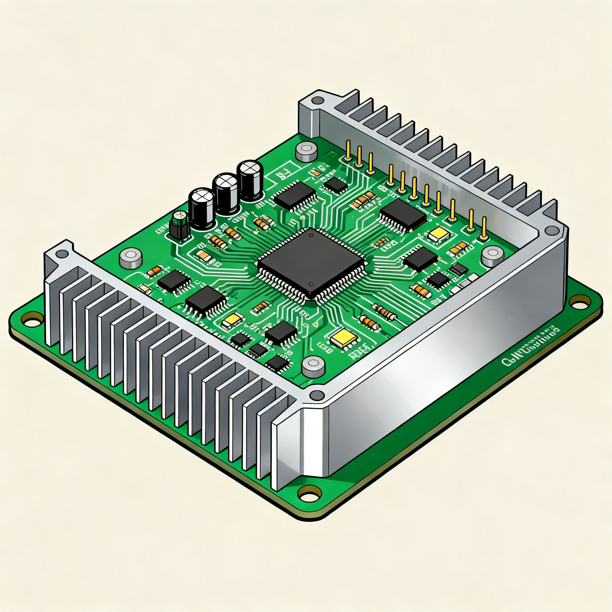
Aluminum-Core PCB Assembly for High-Power LED Lighting: A Field Guide for Engineers
Aluminum-Core PCB Assembly for High-Power LED Lighting: An Engineer's Field Guide If you've ever had an LED array fail six months into a warranty period—and tracked the root cause back to a thermal pa...
Aluminum-Core PCB Assembly for High-Power LED Lighting: An Engineer's Field Guide
If you've ever had an LED array fail six months into a warranty period—and tracked the root cause back to a thermal path you assumed was adequate during design—you already know why substrate selection isn't a footnote. It's the foundation. This field guide is built for engineers and manufacturing buyers who need to make aluminum-core PCB assembly decisions that hold up under thermal load, across production volumes, without surprises on the shop floor or in the field. We'll walk through real failure modes, the MCPCB structure under a thermal lens, substrate trade-offs, assembly process controls, and the questions senior engineers ask before cutting a purchase order.
The Real Cost of Ignoring Thermal Design in High-Power LED Boards
Thermal design mistakes in high-power LED boards don't announce themselves during bring-up. They accumulate silently until a driver mismatch or a dielectric hot spot triggers early lumen depreciation—or worse, a full board-level failure. I've watched engineering teams chase software bugs for weeks, only to discover the real problem was a cheap aluminum-core board with a dielectric layer never designed for the actual junction-to-ambient thermal gradient.
The automotive LED headlight segment offers a particularly unforgiving test case. As documented in LZJPCB's automotive LED headlight engineering analysis, driver mismatches and thermal shortcuts on low-cost aluminum boards have triggered field recalls that dwarf the initial BOM savings. One design team learned this the hard way: routing each LED channel cleanly and maintaining even heat distribution required a 1-on-1 design review with the fabricator's engineers to catch mismatches before the first article reached the factory floor. That design review, which LZJPCB advocates as standard practice, caught three driver-to-load misconfigurations that would have manifested as intermittent flicker in cold-weather operation.
The financial arithmetic is equally brutal in commercial lighting. A high-bay LED fixture running at 150W on an underspecified FR4 board with thermal vias may survive initial burn-in. But after 2,000 hours of thermal cycling, the via barrels crack, the junction temperature creeps past 125°C, and lumen output drops 30%. By that point, the cost of the board itself is irrelevant—you're paying for field service calls, replacement units, and a damaged reputation. According to FastTurnPCBs' MCPCB thermal design guide, aluminum-core boards that combine structural strength with efficient heat dissipation are the difference between a product that lasts 50,000 hours and one that fails at 5,000.
Key Takeaway: The real cost of ignoring thermal design isn't the PCB unit price difference between FR4 and aluminum-core. It's the cumulative cost of field failures, warranty claims, and engineering rework cycles that could have been avoided with a properly specified MCPCB from the start.
Inside the MCPCB Sandwich: Dielectric, Copper, and Aluminum Core Under a Thermal Lens
An aluminum-core PCB—often called a metal-core PCB or MCPCB—is deceptively simple in cross-section but demanding in thermal engineering. The structure is a three-layer sandwich: a copper circuit layer on top, a thermally conductive but electrically insulating dielectric in the middle, and an aluminum base plate at the bottom. Heat generated at the LED junction travels through the solder joint, into the copper pad, across the dielectric, and finally into the aluminum core, which acts as the primary heat spreader. Every interface in that path matters.
The dielectric layer is the bottleneck. Even the best thermally conductive dielectrics operate in the 1.0–2.2 W/mK range—orders of magnitude below copper (≈385 W/mK) or aluminum (≈205 W/mK). This means the dielectric's thermal impedance per unit area determines the entire board-level thermal resistance. If your fabricator can't quote you the measured thermal impedance of their dielectric—not just the bulk conductivity number from a datasheet—you're blind to the most critical variable in the stack-up. PCBWay's aluminum PCB resource notes that the metal core provides efficient heat dissipation precisely because the dielectric is engineered to balance electrical isolation with minimal thermal impedance, a trade-off that varies significantly between material formulations.
The table below compares common dielectric material classes used in MCPCB construction for LED lighting applications, drawing on data from fabricator specifications and published thermal performance benchmarks.
| Dielectric Type | Thermal Conductivity (W/mK) | Typical Thickness (µm) | Breakdown Voltage (kV) | Best Application in LED Lighting |
|---|---|---|---|---|
| Standard epoxy-glass (FR4 replacement) | 0.3–0.5 | 75–150 | 2.5–4.0 | Low-power indicator LEDs, decorative strips |
| Thermally conductive epoxy | 1.0–1.5 | 75–125 | 2.0–3.5 | Mid-power COB arrays, downlights |
| High-performance ceramic-filled epoxy | 1.5–2.2 | 50–100 | 3.0–5.0 | High-power streetlights, stadium floodlights |
| Boron nitride-filled dielectric | 2.5–4.0 | 75–150 | 2.5–4.0 | Automotive headlights, ultra-high-power modules |
| Polyimide-based thin-film dielectric | 0.8–1.2 | 25–50 | 1.5–3.0 | Flexible LED strips, compact modules |
| Direct-bonded copper (DBC) on alumina | 24–28 (alumina layer) | 250–630 | 10–15 | Extreme-power UV-LED arrays, specialty industrial |
The numbers in the table tell only part of the story. What matters in practice is the thermal impedance from junction to ambient, which includes the dielectric, the aluminum core thickness, and any external heatsink interface. PCBSync's LED PCB design guide emphasizes that aluminum-core MCPCBs offer the best balance of thermal performance and cost for most LED applications—but only if the dielectric specification is matched to the actual power density on the board. A 1.0 W/mK dielectric paired with a thick aluminum core and a large heatsink may outperform a 2.2 W/mK dielectric on a thin core with poor heatsink coupling. The system matters.
Tip: When requesting quotes, ask for the dielectric's thermal impedance in °C·cm²/W at the planned thickness, not just the W/mK number. Two materials with identical bulk conductivity can perform differently at different thicknesses due to interfacial resistance effects.
Aluminum vs. Copper vs. Ceramic vs. FR4 for LED Arrays: When Cost, Weight, and Thermal Budget Collide
Selecting the right substrate for a high-power LED array means navigating four legitimate options, each with distinct strengths and failure modes. The choice isn't simply about picking the highest thermal conductivity—it's about matching the substrate to your thermal budget, production volume, mechanical constraints, and field environment. Let's examine each contender.
Aluminum-Core MCPCBs remain the workhorse of LED lighting for good reason. With dielectric thermal conductivities of 1.0–2.2 W/mK and aluminum base thicknesses from 1.0–3.2 mm, they handle power densities up to roughly 15–20 W per square inch without external heatsinks in free-air convection. They're cost-effective, mechanically robust, and widely available in prototype and production volumes. PCBELEC's LED assembly guide confirms that aluminum's thermal conductivity range, combined with its reasonable cost, makes it the most common substrate for LED PCB assembly without requiring external heat sinks for many mid-power designs. Aluminum is also highly recyclable and non-toxic, which matters for end-of-life compliance in commercial lighting projects.
Copper-core boards push thermal performance further, with baseplate conductivity around 385 W/mK, but at a significant weight and cost penalty. They're typically reserved for applications where the aluminum core simply can't spread heat fast enough—think compact module designs with very high LED density where the board doubles as the primary heatsink. Weight becomes a real constraint: copper is roughly 3.3× heavier than aluminum, which impacts mounting hardware, shipping costs, and fixture design for suspended luminaires.
Ceramic substrates (alumina or aluminum nitride) eliminate the polymer dielectric entirely, offering thermal conductivities from 24 W/mK (alumina) to 170+ W/mK (AlN). They're the go-to choice for UV-LED arrays, chip-on-board designs with extreme power density, and applications where the PCB must survive temperatures well above 150°C. The cost, however, is 5–15× that of aluminum-core for equivalent area, and the brittleness of ceramic demands careful mechanical design and handling during assembly.
FR4 with thermal vias remains tempting for cost-driven projects. By filling vias with copper or conductive epoxy under each LED thermal pad, you can create a thermal path through a standard FR4 board to a rear-mounted heatsink. The problem is that thermal via arrays rarely achieve effective conductivity above 5–10 W/mK through the board thickness, and via reliability under thermal cycling is a persistent concern. PCBONLINE's high-power LED PCB guide provides a detailed comparison of all four substrate types, noting that while aluminum and copper dominate for most mainstream designs, ceramic becomes essential when junction temperatures push beyond what polymer-based dielectrics can handle.
| Comparison Metric | Aluminum-Core MCPCB | Copper-Core MCPCB | Ceramic (Alumina/AlN) | FR4 + Thermal Vias | Selection Criteria & Failure Boundary |
|---|---|---|---|---|---|
| Effective Thermal Conductivity (board-level) | 1.0–2.2 W/mK (dielectric-limited) | 1.5–4.0 W/mK (dielectric-limited) | 24–170 W/mK | 3–10 W/mK (via-limited) | Choose Al-core for <15 W/in²; ceramic for >30 W/in² or TJ > 125°C |
| Weight (relative to Al-core) | 1.0× (baseline) | 3.3× | 1.2–1.5× | 0.6–0.8× | Copper adds fixture-level structural cost; aluminum is lighter and suitable for larger assemblies |
| Recyclability & Environmental | Excellent, non-toxic | Excellent | Moderate (brittle, harder to recycle) | Poor (mixed materials) | Al-core wins for end-of-life sustainability in volume lighting |
| Cost per Square Inch (prototype, qty 100) | $0.50–1.50 | $2.00–5.00 | $5.00–20.00+ | $0.30–0.80 | FR4 is cheapest upfront but may require a costly external heatsink and field-failure risk |
| Max Operating Temperature | 130–150°C (dielectric Tg limited) | 130–150°C | 250°C+ (AlN) | 130°C (Tg limited) | Ceramic is essential for sustained high-temp operation |
| Prototype Lead Time (with assembly) | 3–7 days | 5–10 days | 10–20 days | 2–5 days | Al-core offers the best balance of speed and thermal performance for prototyping |
| Typical Dielectric Thickness Range | 50–150 µm | 75–150 µm | N/A (no organic dielectric) | N/A (via-dependent) | Thinner dielectric = lower thermal impedance but higher capacitance and voltage stress |
EBest PCB's comparison of aluminum vs. FR4 captures the core trade-off succinctly: aluminum PCBs perform better in thermal conditions, while FR4 is more flexible in multilayer layouts and low-cost builds. The decision hinges on whether your LED array can tolerate the thermal penalty of FR4 or whether the cost of an aluminum-core board is justified by the reliability gain. JHYPCB's LED PCB manufacturing page highlights that full quality control systems, RoHS compliance, and UL recognition are standard expectations—what differentiates suppliers is how they handle design optimization and engineering support during the substrate selection process.
Practical Rule of Thumb: If your power density exceeds 10 W per square inch, start with aluminum-core. If it exceeds 20 W per square inch, evaluate copper-core. If it exceeds 30 W per square inch and your form factor won't accommodate a large external heatsink, ceramic is likely the right call. For decorative lighting under 5 W per square inch with generous airflow, FR4 with thermal vias may work—but test it under worst-case ambient conditions before committing to volume.
From Reflow Profiles to Solder Wetting: Assembly Steps That Prevent Detached LEDs and Hot-Spot Failures
Aluminum-core PCB assembly demands process discipline that goes beyond standard FR4 reflow recipes. The aluminum baseplate acts as a massive heat sink during soldering, pulling thermal energy away from the solder joints faster than a typical FR4 board ever would. If your reflow profile was developed on FR4 and simply copied to an MCPCB, you're almost certainly under-reflowing your joints. This section covers the shop-floor adjustments that prevent the most common assembly defects on aluminum-core LED boards.
Stencil Design for Thick Copper Planes. Aluminum-core LED boards often use 2–4 oz copper to minimize lateral thermal resistance. Those thick copper layers demand stencil apertures that deliver adequate solder paste volume, especially for large thermal pads under COB LEDs. Use step-up stencils for the thermal pad area, targeting a solder paste coverage of 60–80% on the pad—not 100%. A full-coverage paste print traps volatiles and increases voiding. For SMD LED packages, maintain a stencil thickness of 5–6 mil (125–150 µm) with aperture area ratios above 0.66 to ensure consistent paste release. FastTurnPCBs' MCPCB assembly tips emphasize designing cooler and building longer-lasting products by matching the stencil strategy to the board's thermal mass.
Reflow Profile Adaptation. An aluminum-core board needs a longer soak zone and a higher peak temperature compared to an FR4 equivalent. The soak phase—typically 150–180°C for 90–120 seconds—gives the entire aluminum mass time to reach thermal equilibrium before the reflow zone. The peak temperature should reach 240–250°C at the solder joint for SAC305 lead-free solder, with time above liquidus (TAL) extended to 60–90 seconds. The cooling ramp is equally critical: aim for 2–4°C/second. Cooling too fast creates thermal shock in the dielectric layer; too slow produces coarse grain structures in the solder that reduce fatigue life. BestPCBs' COB LED assembly guide stresses using an appropriate reflow profile and checking solder wetting, component orientation, stand-off, and visible defects after soldering—each of these checkpoints becomes more critical when the board's thermal mass varies across the panel.
| Assembly Parameter | Aluminum-Core MCPCB Target | FR4 Baseline (for reference) | Notes & Inspection Method |
|---|---|---|---|
| Stencil thickness | 5–6 mil (125–150 µm) | 4–5 mil (100–125 µm) | Step stencil for COB thermal pads; verify with SPI |
| Soak temperature & duration | 150–180°C, 90–120 sec | 150–180°C, 60–90 sec | Longer soak compensates for aluminum thermal mass |
| Peak reflow temperature (SAC305) | 240–250°C | 235–245°C | Measure at solder joint, not oven setpoint |
| Time above liquidus (TAL) | 60–90 sec | 45–75 sec | Ensures complete wetting on thick copper pads |
| Cooling ramp rate | 2–4°C/sec | 3–6°C/sec | Slower cooling protects dielectric; avoid thermal shock |
| COB voiding acceptance threshold | <25% of thermal pad area | <25% (same criterion) | X-ray inspection mandatory; cross-section for process validation |
| Stand-off height (COB LEDs) | 50–75 µm minimum | N/A (FR4 rarely used for COB) | Prevents solder bridging under large die; measure post-reflow |
| Fixture material for SMT | Aluminum or titanium pallet | FR4 or composite pallet | Fixture must withstand repeated 250°C cycles without warping |
Voiding Inspection for COB LEDs. The number-one assembly defect on aluminum-core LED boards isn't tombstoning or bridging—it's voiding in the thermal interface material (TIM) under COB LED packages. Voids create localized hot spots that raise the LED junction temperature far above the design target, accelerating lumen depreciation and risking catastrophic delamination. X-ray inspection after reflow is non-negotiable for COB assemblies. Accept no more than 25% void area on the thermal pad, and investigate process adjustments if voids consistently exceed 15%. Root causes typically include insufficient preheat drying of the solder paste, excessive flux volatiles trapped under a large thermal pad, or inadequate stand-off height preventing proper outgassing. BestPCBs' COB aluminum PCB manufacturing guide explicitly calls out solder wetting, component orientation, stand-off, and visible defect inspection as the mandatory post-reflow checkpoints—each one a direct defense against hot-spot failures.
Fixture and Handling Considerations. Aluminum-core boards are heavier and stiffer than FR4, which means standard SMT conveyors and reflow carriers may need adjustment. Boards with aluminum bases of 1.6 mm or thicker often require dedicated fixture pallets that maintain flatness through the reflow oven. Warpage above 0.5% of the board diagonal can cause inconsistent solder paste printing and tombstoning on smaller SMD LEDs. PCBELEC's turnkey LED assembly service incorporates these fixture considerations into their quality control system, treating board flatness as a process input variable rather than a post-assembly inspection criterion.
Tip: Before committing to a volume production run, run a thermal profile on the actual reflow oven with a populated aluminum-core test board and thermocouples at multiple locations—including the largest COB thermal pad, the smallest SMD LED, and the board edge. The temperature delta across the board can exceed 15°C on thick aluminum substrates, and that's enough to create a bimodal distribution of solder joint quality.
What Engineers Who Live with Thermal Issues Actually Ask (Before Ordering)
After years of troubleshooting LED thermal failures, certain questions come up repeatedly—not from junior designers, but from senior engineers who've been burned before and know exactly where the risks hide. Here are the questions that deserve straight answers before you release a purchase order for aluminum-core LED boards.
Q: What thermal conductivity number should I trust from my fabricator, and how do I verify it?
Most fabricators quote bulk dielectric thermal conductivity in the 1.0–2.2 W/mK range for standard aluminum-core boards. That number is typically a material datasheet value, not a measurement of the dielectric layer as fabricated on your specific board. What you actually care about is the thermal impedance of the assembled dielectric layer—the combination of its bulk conductivity, thickness, and any interfacial resistances at the copper-dielectric and dielectric-aluminum boundaries. Ask your fabricator for the measured thermal impedance in °C·cm²/W at the specific dielectric thickness they're quoting. If they can't provide this, request a cross-sectional sample with IPC-TM-650 2.5.7 thermal conductivity test results. A reputable fabricator can typically provide this data for their standard dielectric formulations. JHYPCB's LED PCB manufacturing specifications note thermal conductivities from 1–9 W/mK using advanced metal-core technology—the higher end of this range typically involves ceramic-filled or boron nitride-filled dielectrics, and the number should always be tied to a specific test method.
Q: Can I use thermal vias on an aluminum-core board, or is that only for FR4?
Thermal vias are uncommon on metal-core PCBs because the aluminum baseplate already functions as a continuous heat spreader across the entire board area. The entire point of the MCPCB structure is to conduct heat vertically through the thin dielectric into the aluminum—vias from the copper pad down to the metal core would create a direct electrical short unless carefully isolated, which adds cost and complexity while providing marginal thermal benefit. However, vias are sometimes used when the dielectric layer is exceptionally thick (above 150 µm) and the power density is high enough that the dielectric becomes the dominant thermal bottleneck. In those rare cases, electrically isolated thermal vias—essentially blind vias stopped at the dielectric-aluminum interface with a thin isolation layer—can be implemented. For 95% of LED applications on aluminum-core boards, skip the vias, select a thinner high-performance dielectric, and let the aluminum slab do its job.
Q: What's the biggest assembly defect with COB LEDs on aluminum, and how do I catch it?
Voiding in the solder or thermal interface material under the COB LED's thermal pad is the single biggest assembly defect on aluminum-core LED boards. Voids create localized regions of high thermal resistance, producing hot spots that can push the LED junction temperature 20–30°C above the design target. The failure mode is insidious because the board passes electrical test and initial light-output measurements, but the voids accelerate phosphor degradation and solder fatigue under thermal cycling. Detection requires X-ray inspection after reflow—visual inspection and AOI cannot see under the COB package. The acceptance criterion widely adopted in the industry is less than 25% void area on the thermal pad, though many automotive and high-reliability applications tighten this to 15%. BestPCBs' COB LED assembly guide emphasizes X-ray inspection as a mandatory process step, not an optional add-on. If your contract manufacturer pushes back on X-ray for COB assemblies, find another CM.
Q: How do I avoid paying for exotic ceramics when aluminum will do the job?
Start by mapping your LED's junction-to-ambient thermal resistance requirement from the datasheet. For a typical high-power LED with a maximum junction temperature of 125°C, a thermal pad temperature of 85°C, and an ambient of 45°C, you need a total Rth(j-a) below approximately 6.5°C/W for a 6W LED. If a standard MCPCB with a 1.5 W/mK dielectric and a modest external heatsink keeps the junction below its rated temperature under worst-case ambient conditions, there is zero technical justification for copper or ceramic. PCBONLINE's substrate decision framework provides a logical progression: determine your power density, calculate the required thermal resistance, and match it to the most cost-effective substrate that meets the requirement with margin. Ceramics become necessary only when form factor constraints force high power density into a small footprint, or when ambient temperatures exceed what polymer-based dielectrics can handle. Over-specifying the substrate is an expensive form of thermal over-engineering that rarely improves field reliability.
Q: What are realistic prototype lead times for aluminum-core boards with assembly?
Many established fabricators quote 3–5 days for sampling and 7–15 days for production runs on standard aluminum-core PCBs with assembly. JHYPCB's published lead times reflect this industry norm: 24-hour quote turnaround, 3–5 days for sampling, and 7–15 days for production, with free DFM checks included. However, non-standard dielectric thicknesses, custom aluminum core alloys, or unusual layer counts can add 3–7 days of tooling time. Always confirm whether the quoted lead time includes DFM review, stencil fabrication, and SMT fixture preparation. A quote that looks faster on paper but omits fixture lead time will actually be slower when the assembly line is ready to run. For time-sensitive projects, ask whether the fabricator stocks your preferred dielectric material in standard thicknesses—this is often the single largest variable in prototype turnaround time.
Q: If my LED drivers keep mismatching in the field, is it the board or the design?
Driver mismatch failures in the field are overwhelmingly a design-level problem, not a PCB fabrication defect. The root cause is typically a misalignment between the driver's output characteristics (constant-current setpoint, voltage compliance range, dimming interface timing) and the LED load's forward voltage and thermal coefficient. A 1-on-1 design review with the fabricator's engineering team before tape-out is one of the highest-leverage activities you can perform. LZJPCB's automotive headlight engineering practice demonstrates this directly: their engineering review process catches driver-to-load mismatches before boards reach the factory floor, preventing the costly field recalls that result from cheap quotes with poor thermal and electrical design support. If your current fabricator doesn't offer this kind of engineering review, you're leaving a known failure mode unaddressed.
The six questions above reflect the concerns engineers raise after they've been through a few design cycles and learned where the real risks live. They're not academic—they're operational. If your fabricator can't answer them clearly and with specific data, you're not working with the right partner.
References & Further Reading
- Aluminum PCB Guide: MCPCB Thermal Design for LED Drivers & Ballasts – FastTurnPCBs
- COB LED Aluminum PCB Manufacturing for High-Power LED Modules – BestPCBs
- Automotive LED Headlight PCB Assembly and Manufacturing – LZJPCB
- High-Power LED PCB: Aluminum, Copper, Ceramic, or FR4? – PCBONLINE
- LED PCB Manufacturing & Assembly | Aluminum LED Circuit Board – JHYPCB
- Rapid Aluminium Core PCB from Prototype to Assembly – EBest PCB
- LED PCB Assembly Services: Substrate & Thermal Guide – PCBELEC
- Premium Aluminum PCB Manufacturer – PCBWay
- LED PCB Design: SMD, Light Circuits & VU Meter Layout Guide – PCBSync
This field guide was prepared by the engineering team at NovaPCBA, where aluminum-core PCB assembly for high-power LED lighting is a core manufacturing competency. Whether you need prototype sampling in 3–5 days or volume production with full DFM review, our engineering team can help you navigate substrate selection, thermal design validation, and assembly process optimization. Contact us to discuss your next LED lighting project.