Introduction
In the realm of electronic design, ensuring the reliability of printed circuit boards (PCBs) is paramount, especially in high-reliability applications such as aerospace, medical devices, and automotive systems. With the increasing complexity of electronic components and the demand for more compact and efficient designs, effective PCB testing methods have become an essential part of the design and manufacturing process. This article aims to provide a comprehensive guide to effective PCB testing methods, focusing on component specifications, datasheets, selection criteria, and application circuits, to ensure high reliability and performance.
Technical Overview
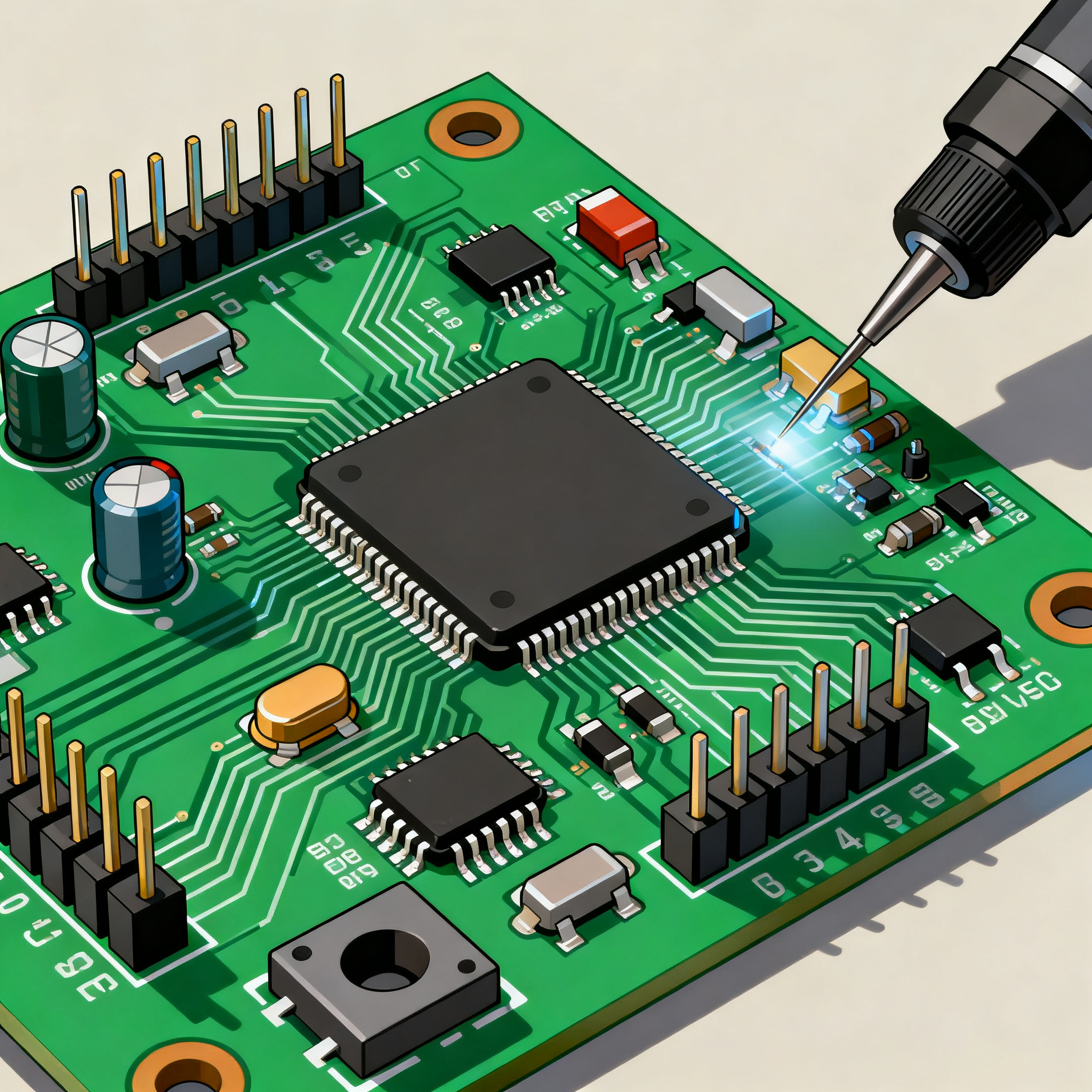
To understand PCB testing methods, it's crucial to grasp the core concepts and architecture of PCBs. A PCB serves as the foundation for mounting and interconnecting electronic components, providing both mechanical support and electrical connections. The architecture of a PCB includes multiple layers of conductive tracks, pads, and other features etched from copper sheets laminated onto a non-conductive substrate. Key principles in PCB design include signal integrity, power distribution, thermal management, and electromagnetic compatibility.
The design process begins with schematic capture, where the electrical circuit is defined. This is followed by layout design, where components are placed, and routing is done on the PCB. High-reliability applications require adherence to stringent standards and guidelines, such as those outlined by the IPC, to ensure durability and performance under extreme conditions. Testing methods for PCBs include in-circuit testing (ICT), functional testing, boundary scan, and environmental stress screening (ESS), each serving a unique role in verifying different aspects of the PCB's performance.
Detailed Specifications
When selecting components for high-reliability PCBs, understanding their specifications is crucial. Specifications include parameters like CPU speed, memory, power requirements, and package type, which influence the overall performance and compatibility of the PCB. These specifications are typically found in datasheets provided by component manufacturers and play a vital role in the selection process.
| Specification | Details | Comments |
| CPU Speed | 1.2 GHz | High-speed processing for complex applications |
| Memory | 4GB DDR4 | Sufficient for most applications |
| Peripherals | USB, I2C, SPI | Supports multiple communication protocols |
| Power | 3.3V | Standard low-voltage operation |
| Package | LQFP | Compact form factor for space-constrained designs |
| Operating Temperature | -40°C to 85°C | Suitable for industrial applications |
| Storage Temperature | -55°C to 125°C | Ensures durability in harsh environments |
| MTBF | 100,000 hours | High reliability for critical applications |
| RoHS Compliance | Yes | Environmentally friendly |
| Connectivity | Wi-Fi, Bluetooth | Supports wireless communication |
| Dimensions | 10mm x 10mm | Compact size for integration |
Key Takeaways from the Specifications
The core specifications of a component dictate its suitability for specific applications. For instance, a CPU speed of 1.2 GHz provides the necessary processing power for data-intensive tasks, while 4GB of DDR4 memory ensures smooth operation. The inclusion of peripherals like USB, I2C, and SPI allows for versatile interfacing options, critical for integrating various modules. The power requirement of 3.3V is standard for low-power designs, ensuring energy efficiency. The operating and storage temperature ranges highlight the component's ability to withstand extreme conditions, making it ideal for industrial applications. The high MTBF (Mean Time Between Failures) indicates the component's reliability, essential for critical systems. Lastly, RoHS compliance ensures the component is environmentally friendly, aligning with global sustainability efforts.
| Parameter | Value | Comments |
| Supply Voltage | 3.3V | Standard voltage for low-power applications |
| Operating Current | 150mA | Moderate current consumption |
| Max Current | 200mA | Peak current handling capability |
| Input Logic High Voltage | 2.0V | Minimum voltage for logic high |
| Input Logic Low Voltage | 0.8V | Maximum voltage for logic low |
| Output Logic High Voltage | 2.9V | Output voltage level for logic high |
| Output Logic Low Voltage | 0.4V | Output voltage level for logic low |
| Propagation Delay | 10ns | Fast switching speed |
| Rise Time | 5ns | Quick signal rise time |
| Fall Time | 5ns | Quick signal fall time |
| I/O Pins | 32 | Ample pins for interfacing |
| ESD Protection | 2kV | Robust electrostatic discharge protection |
Practical Implications
Understanding the electrical characteristics of components is crucial for designing reliable PCBs. The supply voltage of 3.3V and operating current of 150mA indicate the power requirements for the component, which influence the power supply design. The input and output logic voltage levels are essential for ensuring compatibility with other components in the circuit. Fast propagation delay and quick rise/fall times are critical for high-speed applications, reducing signal distortion. The availability of 32 I/O pins provides flexibility for interfacing with other devices, while ESD protection ensures the component's durability against electrostatic discharge. These parameters guide engineers in designing circuits that meet performance and reliability standards.
| Application | Configuration | Benefits |
| Industrial Automation | High-speed CPU, robust I/O | Reliable operation in harsh environments |
| Medical Devices | Low power, compact size | Energy-efficient and space-saving |
| Automotive Systems | High temperature range, ESD protection | Durability under extreme conditions |
| Consumer Electronics | Wireless connectivity, multimedia support | Enhanced user experience |
| Telecommunications | Fast switching, high data rate | Efficient data transmission |
| Aerospace | High reliability, MTBF | Critical for mission success |
| Smart Home Devices | IoT integration, low power | Seamless connectivity and operation |
Application Guidelines
Different applications require specific configurations to optimize performance and reliability. In industrial automation, a high-speed CPU and robust I/O configuration ensure reliable operation in demanding environments. Medical devices benefit from low power consumption and compact size, crucial for portable and energy-efficient designs. Automotive systems require components that can withstand high temperature ranges and have ESD protection to ensure durability. Consumer electronics focus on wireless connectivity and multimedia support to enhance user experience. In telecommunications, fast switching and high data rates are essential for efficient data transmission. Aerospace applications demand high reliability and MTBF, critical for mission success. Smart home devices benefit from IoT integration and low power consumption, enabling seamless connectivity and operation.
Design Considerations
Designing a PCB for high-reliability applications involves several critical considerations. Firstly, component selection is paramount. Engineers must choose components with specifications that meet the application's performance and environmental requirements. This includes evaluating datasheets for parameters such as operating temperature, power consumption, and MTBF. Additionally, adherence to industry standards, such as IPC-A-610 and IPC-2221, ensures quality and reliability in design and manufacturing.
Signal integrity is another crucial aspect. Proper routing techniques, such as controlled impedance and differential pair routing, minimize signal distortion and interference. Power distribution is equally important, requiring careful planning of power planes and decoupling capacitors to ensure stable voltage levels across the PCB. Thermal management is essential to prevent overheating, often achieved through thermal vias, heat sinks, and proper component placement.
Electromagnetic compatibility (EMC) must also be considered, especially in environments with high electromagnetic interference (EMI). Shielding, filtering, and grounding techniques help mitigate EMC issues. Finally, thorough testing, including ICT, functional testing, and ESS, verifies the PCB's performance and reliability before deployment.
Step-by-Step Implementation
Implementing a high-reliability PCB design involves several detailed steps:
- Define Requirements: Begin by clearly defining the application's requirements, including performance, environmental, and regulatory needs.
- Select Components: Choose components that meet the defined requirements, focusing on specifications, datasheets, and reliability ratings.
- Create Schematic: Develop a detailed schematic diagram, ensuring all connections and components are accurately represented.
- Design Layout: Design the PCB layout, considering factors such as signal integrity, power distribution, and thermal management.
- Simulate Design: Use simulation tools to validate the design, checking for issues like signal integrity and thermal performance.
- Fabricate PCB: Work with a reputable manufacturer, adhering to IPC standards for quality and reliability.
- Assemble Components: Assemble the PCB, ensuring proper placement and soldering of components.
- Test PCB: Conduct thorough testing, including ICT, functional testing, and ESS, to verify performance and reliability.
Common Issues & Solutions
High-reliability PCBs can encounter several common issues, each requiring specific solutions:
- Signal Integrity Issues: Use controlled impedance routing and differential pairs to minimize signal distortion.
- Thermal Management Problems: Implement thermal vias, heat sinks, and proper component placement to dissipate heat effectively.
- EMC/EMI Interference: Apply shielding, filtering, and grounding techniques to mitigate electromagnetic interference.
- Component Failure: Choose high-quality components with appropriate reliability ratings and conduct thorough testing.
- Power Distribution Challenges: Plan power planes and use decoupling capacitors to ensure stable voltage levels.
- Manufacturing Defects: Follow IPC standards and work with reputable manufacturers to ensure quality fabrication and assembly.
Applications & Use Cases
High-reliability PCBs find applications in various industries, each with unique use cases:
- Aerospace: Used in avionics systems for navigation, communication, and control, where reliability is critical for mission success.
- Medical Devices: Integrated into life-saving equipment like pacemakers and diagnostic machines, requiring precision and reliability.
- Automotive Systems: Employed in safety-critical systems like airbags and anti-lock braking systems, ensuring robust performance under extreme conditions.
- Industrial Automation: Utilized in control systems and robotics, providing reliable operation in harsh industrial environments.
- Telecommunications: Incorporated into network infrastructure for high-speed data transmission and connectivity.
Selection & Sourcing Guide
Selecting and sourcing components for high-reliability PCBs requires careful consideration. Engineers should prioritize components with proven reliability and performance, verified through datasheets and reliability ratings. Sourcing from reputable suppliers ensures quality and availability. For a comprehensive selection of components, visit
IC Online.
FAQ
- What are the key factors in selecting components for high-reliability PCBs? Consider specifications, reliability ratings, and environmental requirements.
- How do I ensure signal integrity in PCB design? Use controlled impedance routing and differential pairs to minimize distortion.
- What testing methods are used for high-reliability PCBs? In-circuit testing, functional testing, and environmental stress screening are common methods.
- How can I manage thermal issues in PCB design? Implement thermal vias, heat sinks, and proper component placement.
- What standards should I follow for high-reliability PCB design? Adhere to IPC standards like IPC-A-610 and IPC-2221.
- How do I mitigate EMC/EMI issues? Apply shielding, filtering, and grounding techniques to reduce interference.
- What is the importance of MTBF in component selection? MTBF indicates the component's reliability and expected lifespan.
- How do I ensure quality in PCB fabrication and assembly? Work with reputable manufacturers and follow industry standards.
- What role does simulation play in PCB design? Simulation helps validate the design, checking for potential issues before fabrication.
- Why is RoHS compliance important in component selection? RoHS compliance ensures components are environmentally friendly and free from hazardous substances.
Conclusion
In high-reliability applications, effective PCB testing methods and meticulous design considerations are crucial for ensuring performance and durability. By understanding component specifications, adhering to industry standards, and implementing thorough testing, engineers can create PCBs that meet the stringent requirements of critical applications. As technology advances, staying informed and utilizing reliable resources will be key to maintaining high standards in electronic design and manufacturing.