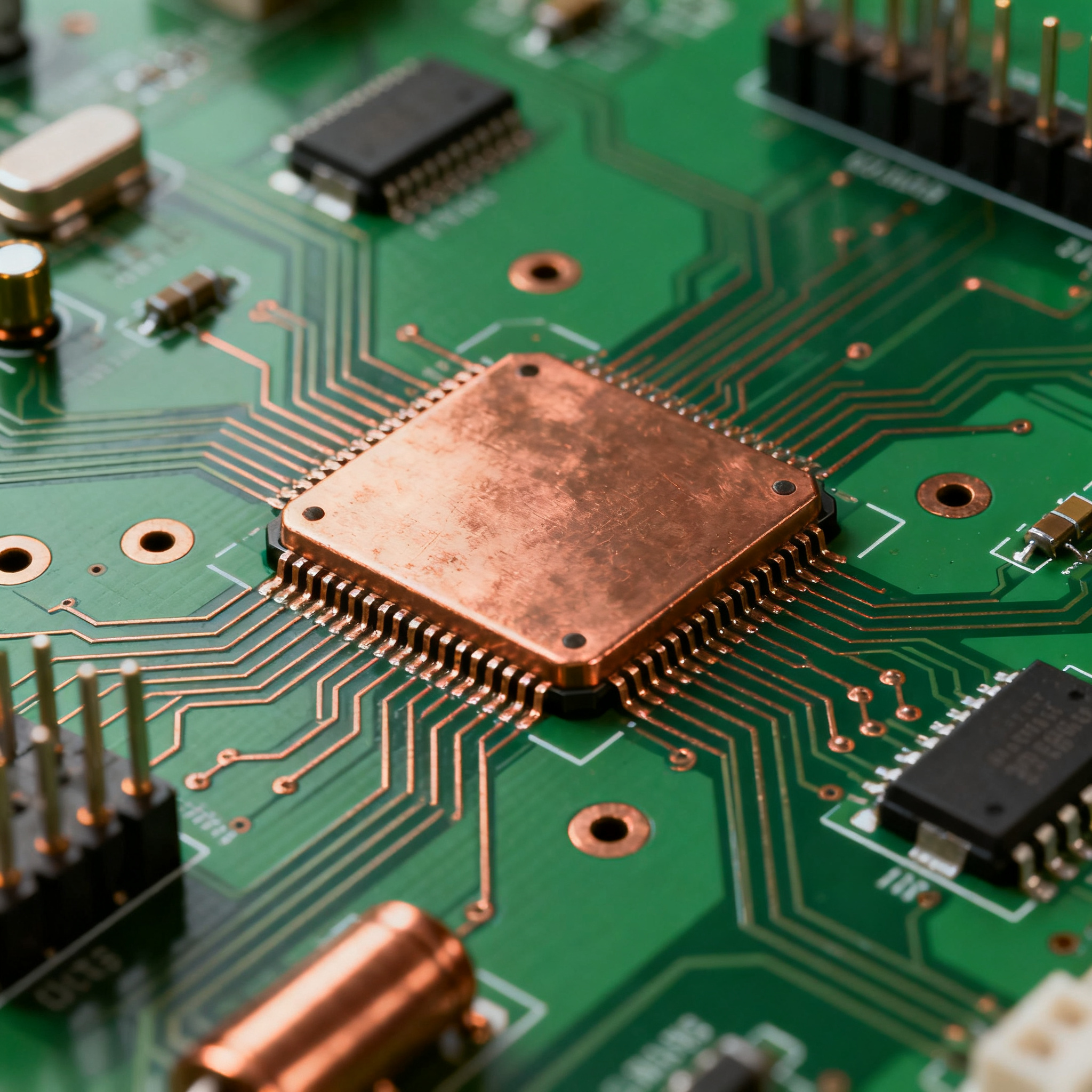
5 Cost-Saving Tips for Sourcing Heavy Copper PCBs from a Renewable Energy Electronics Manufacturer
Tip 1: Lock in Volume Forecasts Early to Sidestep Rush Charges and Allocation Quotas The heavy copper PCB supply chain entered 2026 under pressure that few procurement teams anticipated. Copper prices...
Tip 1: Lock in Volume Forecasts Early to Sidestep Rush Charges and Allocation Quotas
The heavy copper PCB supply chain entered 2026 under pressure that few procurement teams anticipated. Copper prices have climbed roughly 30% year-over-year, while epoxy resin lead times—once a predictable three weeks—have stretched to 15 weeks in constrained segments. The upstream picture is even tighter: some copper-clad laminate (CCL) suppliers now quote six-month lead times and have imposed quota systems that ration available capacity among customers. For renewable energy OEMs sourcing heavy copper boards for solar inverters, wind converters, and battery management systems, these aren't abstract headlines—they're the difference between shipping product on schedule and paying punitive rush charges to keep a production line moving.
The root cause is structural. AI-driven demand for high-performance computing substrates is absorbing a growing share of global CCL output, and raw material bottlenecks—from copper foil to specialty prepregs—haven't eased. PCBCool's 2026 shortage analysis puts the question bluntly: ask whether the specified CCL, prepreg, copper foil, and stackup can be sourced within your required production window. If your manufacturer can't answer that question with a confirmed allocation, your lead time is already at risk.
The financial penalty for reactive sourcing is steep. When a heavy copper PCB order hits the factory floor as a fast-turn job, prioritized scheduling and rushed material procurement can inflate costs by 20–50%, as documented in JHYPCB's cost factor guide. On a $50,000 production run, that's an extra $10,000 to $25,000—budget that could have funded a second prototype spin or covered NRE for a design revision.
Pica Manufacturing's 2026 sourcing report confirms that epoxy resin and copper increases are not temporary blips. The same report notes that DigiTimes observed quota systems being imposed in constrained segments, meaning even established buyers can't assume open access to their preferred laminates. PCBMay's guidance reinforces the solution: strategic forecasting, flexible stackups, and strong supplier partnerships are the three pillars that separate programs that stay on schedule from those that don't.
Tip: Lock in quarterly volume forecasts with your heavy copper PCB manufacturer at least 12 weeks before production. This gives them the leverage to reserve CCL, prepreg, and copper foil allocations before spot-market pricing takes over. If your demand is lumpy, negotiate a capacity reservation agreement that guarantees a minimum monthly slot in exchange for a modest deposit—far cheaper than absorbing 20–50% rush premiums when a purchase order lands without warning.
Tip 2: Decode the True Cost of Heavy Copper — From Foil Thickness to Lamination Cycles
Heavy copper PCBs are defined by copper weights exceeding the standard 1 oz (35 µm) baseline—typically 3 oz (105 µm) and above, with some renewable energy applications pushing to 6 oz, 10 oz, or even 20 oz for extreme current-carrying requirements. PCBgogo's renewable energy PCB guide explains that heavy copper layers carry higher current loads without excessive resistive heating, which is why they're indispensable in high-power clean energy systems. NCAB Group's technical specifications confirm that typical heavy copper capabilities include copper thicknesses over 3 oz with track/gap designs engineered for high-current, high-temperature environments.
But every additional ounce of copper adds cost through mechanisms that aren't always transparent on a quote. Understanding these cost drivers is the first step toward challenging unnecessary thickness increases and negotiating from a position of knowledge.
| Cost Driver | Impact per Ounce Increase | Why It Matters for Renewable Energy PCBs |
|---|---|---|
| Plating time | 30–50% longer per additional oz | Ties up plating tanks; increases labor and energy cost per panel |
| Etching complexity | Requires step etching or differential etching | Thicker copper demands longer etch times and tighter process control to avoid undercut |
| Lamination cycles | Additional press cycles for weights >4 oz | Each cycle adds 2–4 hours of press time and increases the risk of resin starvation |
| Prepreg selection | Higher resin content required | Thicker copper demands more resin flow to fill gaps; specialty prepregs cost 2–3× standard |
| Drill wear | 20–30% reduction in drill bit life | Heavy copper accelerates tool wear; more frequent bit changes increase process cost |
| Yield loss | 2–5% additional scrap per heavy copper layer | Plating voids, delamination, and over-etch defects rise with copper thickness |
| Minimum trace/space | Increases roughly 1:1 with copper weight | 6 oz copper typically requires 6 mil minimum trace/space; limits design density |
| Thermal stress during soldering | Higher thermal mass extends reflow dwell time | Assembly requires profile adjustments; can increase assembly cost by 5–10% |
The cost-per-ounce curve is not linear. Moving from 3 oz to 4 oz might add 15–20% to the bare board cost, but jumping from 4 oz to 6 oz can add 30–40% because it often triggers an additional lamination cycle and requires a step up in prepreg grade. JHYPCB's pricing analysis notes that processes like heavy copper demand specialized equipment and expertise, and shorter lead times compound these base costs by 20–50%.
Key Takeaway: Before accepting a manufacturer's copper weight recommendation, ask for a cost breakdown that separates plating, lamination, and material premiums. If the design can meet current-carrying requirements at 4 oz instead of 6 oz, the savings can fund an entire DFM optimization cycle.
Tip 3: Weigh Domestic vs. Offshore Sourcing and the Hidden Premium of Fast-Turn Lead Times
Sourcing heavy copper PCBs for renewable energy projects involves a structural choice: domestic manufacturing with shorter logistics chains and higher labor rates, or offshore production with lower unit costs but longer lead times and tariff exposure. The decision becomes more complex when fast-turn requirements enter the equation, because expedited orders carry premiums that can erase the offshore cost advantage entirely.
AllPCB's should-cost analysis quantifies one piece of the puzzle: expedited production or delivery of PCB electronic parts can increase costs by 10–25%, especially when components or materials are sourced internationally. Vexos's 2025 pricing review identifies material selection, stack-up optimization, manufacturability considerations, and global sourcing strategies as the four levers that most directly influence total cost. Aivon's cost reduction framework adds that evaluating overseas versus domestic suppliers requires navigating trade-offs in lead times and tariffs—there is no universal answer, only a project-specific optimum.
| Comparison Metric | Domestic Heavy Copper Supplier | Offshore Heavy Copper Supplier | Selection Criteria & Failure Boundary |
|---|---|---|---|
| Base PCB unit cost (4 oz, 4-layer) | $18–$28 per panel (typical) | $10–$18 per panel (typical) | Offshore wins on unit price, but only above 500–1,000 panel volumes |
| Standard lead time | 3–5 weeks | 6–10 weeks (including freight) | Choose domestic if project timelines are <8 weeks from PO to delivery |
| Expedited lead time premium | 10–20% for 2-week turn | 25–40% for 4-week turn (air freight included) | Expedited offshore often exceeds domestic standard pricing |
| Tariff exposure | None (domestic content) | Section 301 tariffs: 25% on PCB imports from China | Tariffs can add $2.50–$7.00 per panel; factor into total landed cost |
| Quality recourse | Direct communication; faster rework cycles | Time zone delays; return shipping costs for non-conforming lots | If field reliability is mission-critical, domestic reduces mean time to resolution |
| Material traceability | Typically full batch traceability to laminate supplier | Varies; may use aggregated material lots | Renewable energy OEMs requiring full traceability should verify offshore documentation |
| Minimum order quantity (MOQ) | Often 5–25 panels | Often 50–100 panels | Prototype and pilot builds favor domestic; volume production favors offshore |
One risk that procurement teams sometimes underestimate is the false economy of unauthorized sourcing channels. When price pressure mounts, the temptation to source outside authorized distributor networks grows—and the consequences can be severe. Accuris's 2026 component cost analysis reports that 50% of organizations experienced six or more post-installation issues in the past year, and 67% incurred $50,000 or more in cost per incident, including recall, rework, warranty claims, and brand damage. For heavy copper PCBs in renewable energy applications—where field failures can mean inverter downtime, lost energy production, and safety hazards—the cost of a single quality escape dwarfs any per-panel savings from unvetted suppliers.
Tip: Run a total landed cost comparison that includes unit price, tariffs, freight, expedite premiums, and an estimated cost of quality (scrap rate × rework cost). For most renewable energy programs with moderate volumes and tight development timelines, a hybrid strategy—domestic supplier for NPI and pilot builds, offshore for steady-state production—delivers the best balance of cost and responsiveness.
Tip 4: Shave Fabrication Costs with DFM: Panelization, Trace Width, and Layer Count
Design-for-manufacturability (DFM) is the single highest-leverage cost reduction tool available to engineers sourcing heavy copper PCBs. Unlike negotiating price with a supplier—which shifts margin from one party to another—DFM eliminates cost at the source by reducing material consumption, process steps, and yield loss. The principles are well established, but applying them to heavy copper designs requires copper-weight-specific judgment.
Aivon's cost reduction research identifies minimizing layer counts, optimizing trace widths, and incorporating panelization techniques as three design best practices that directly reduce fabrication and assembly fees. AllPCB's guide to renewable energy PCB design reinforces the importance of advanced materials, simulation tools, and rigorous testing—but also notes that design choices made early in the development cycle determine the cost floor that no amount of procurement negotiation can break through.
Here are four actionable DFM strategies specifically for heavy copper renewable energy PCBs:
- Minimize layer count through intelligent stackup design. Every additional layer adds a complete lamination cycle, doubling or tripling the press time for heavy copper boards. Before adding a layer for signal routing, explore whether wider trace spacing or a hybrid stackup (heavy copper on outer layers, standard 1 oz on inner layers) can absorb the routing density. PCBCool's shortage strategies and PCBMay's flexible stackup advice both emphasize that stackup flexibility is a competitive advantage when specific laminates are on allocation.
- Optimize trace widths for current, not habit. Heavy copper traces carry high current, but wider isn't always better. Use IPC-2152 conservative charts or thermal simulation to determine the minimum trace width that meets your current-carrying requirement with acceptable temperature rise. A trace that's 20% wider than necessary consumes 20% more copper, increases panel weight, and may force a larger board outline—all of which compound cost.
- Design for panelization from day one. Panel utilization—the percentage of the production panel occupied by your boards—directly determines material cost per unit. Heavy copper panels are more expensive per square inch than standard panels, so every percentage point of wasted space carries a higher dollar penalty. Add breakaway rails, fiducials, and tooling holes early in layout, and work with your manufacturer to optimize the array configuration for their specific panel size. Aivon's volume-based approaches, including just-in-time manufacturing and bulk purchasing, amplify the savings from good panelization.
- Simulate before specifying. AllPCB's design guide urges engineers to leverage simulation tools to validate thermal and electrical performance before locking the stackup. A thermal simulation that confirms a 4 oz plane can handle the required current with a 15°C rise is far cheaper than defaulting to 6 oz "just to be safe." The cost of simulation software or consulting time is trivial compared to the per-panel premium of over-specified copper.
Cost savings from DFM must not come at the expense of reliability. PCBgogo's renewable energy PCB overview emphasizes that manufacturers serving clean energy markets should manufacture to IPC Class 2 and Class 3 specifications, with full traceability and rigorous electrical testing on every order. When you propose a stackup change or trace width reduction, ask your manufacturer to confirm that the revised design still meets the relevant IPC class requirement and can pass their standard electrical test regimen.
Tip 5: Right-Size Copper Weight for Your Inverter, Converter, or BMS — Don't Over-Specify
Over-specification is the silent cost killer in heavy copper PCB sourcing. Engineers, understandably risk-averse when designing power electronics that will operate in the field for 15–20 years, often default to the highest copper weight they've seen in a reference design—or add a "safety factor" that compounds across every layer of the stackup. The result is a board that costs 40–60% more than necessary, with no corresponding improvement in field reliability.
PCBgogo's application notes on heavy copper for renewable energy make the point clearly: heavy copper PCBs use thicker copper layers to carry higher current loads without excessive resistive heating, which makes them well suited to high-power systems—but "heavy" is a range, not a single specification. NCAB's high-power application examples span EV chargers, high-current systems, power storage systems, and base stations—each with different current densities, thermal environments, and reliability requirements. A one-size-fits-all copper weight serves none of them optimally.
| Renewable Energy Application | Typical Current Range | Recommended Copper Weight | Over-Specification Risk |
|---|---|---|---|
| Solar microinverter (300–500 W) | 5–15 A continuous | 2–3 oz on power planes | Specifying 4 oz adds ~20% cost with negligible thermal benefit |
| String inverter (10–50 kW) | 20–60 A on DC bus | 4–6 oz on DC bus layers | 6 oz may be justified for 60 A designs; 4 oz often suffices at 30 A with adequate trace width |
| Central inverter (>100 kW) | 100–300 A on main bus | 6–10 oz, often with busbar augmentation | Above 10 oz, consider external busbars rather than pushing PCB copper to its process limit |
| Wind converter (2–5 MW) | 50–150 A per phase | 4–8 oz on output phases | Hybrid stackup with heavy copper on outer layers and standard copper on inner signal layers reduces cost 25–35% |
| Battery management system (BMS) | 10–50 A balancing current | 3–5 oz on balancing traces | BMS boards often have dense digital sections; over-specifying copper on all layers limits routing density |
| EV charger (Level 2, 7–22 kW) | 30–80 A | 4–6 oz on power delivery path | Thermal simulation can often justify 4 oz where 6 oz was originally specified |
The right-sizing methodology is straightforward but underused. Start with the maximum continuous current the trace or plane must carry, add the ambient temperature inside the enclosure (which can reach 65–85°C in a sealed inverter), and define the allowable temperature rise above ambient. Then consult IPC-2152 conservative charts—not the older IPC-2221 curves, which can be overly conservative for heavy copper—or run a quick thermal simulation. PCBgogo's compliance and testing overview reinforces that manufacturers with renewable energy expertise can often provide derating guidance based on empirical data from similar designs.
Key Takeaway: A 3 oz copper layer on a 10 mm wide trace can carry approximately 20 A with a 10°C temperature rise. If your design operates at 15 A with forced-air cooling, 3 oz is almost certainly sufficient—and the 25% cost premium for 4 oz buys you nothing except a thicker board. Use simulation and derating curves to challenge every copper weight specification, and treat "we've always used 6 oz" as a hypothesis to be tested, not a requirement to be met.
Heavy Copper PCB Sourcing FAQ for Renewable Energy Projects
Q: How do I determine the right copper weight for a solar inverter or wind converter PCB?
Base your decision on three parameters: maximum continuous current, ambient operating temperature inside the enclosure, and allowable temperature rise. Use IPC-2152 conservative charts rather than the older IPC-2221 standard, which can overestimate required trace widths for heavy copper. A 3 oz copper layer on a 10 mm wide trace can carry approximately 20 A with a 10°C rise, but derating is critical for high-temperature environments—at 65°C ambient, the same trace may need to be 30–40% wider or step up to 4 oz. Thermal simulation tools provide the most accurate guidance and are worth the investment before locking a stackup.
Q: What is the typical cost premium for 3 oz vs 4 oz copper, and when does it justify the added expense?
Moving from 3 oz to 4 oz copper typically increases bare board cost by 15–25%, driven by longer plating time, additional etch complexity, and potentially higher-resin-content prepregs. The premium is justified only when the design requires a meaningful boost in current capacity—for example, a 60 A DC bus that would require impractically wide traces at 3 oz—or when reduced resistive losses (I²R) translate to lower system-level cooling costs that offset the PCB premium over the product's service life. For most 15–30 A applications, 3 oz with optimized trace widths delivers equivalent electrical performance at lower cost.
Q: Can I use a hybrid stackup (heavy copper on outer layers, standard on inner) to reduce cost?
Yes, and this is one of the most effective cost-saving techniques for renewable energy PCBs. Heavy copper (3–6 oz) on outer layers carries high current where it's needed, while inner layers use standard 1 oz copper for signal routing, low-power distribution, or ground planes. This approach reduces overall copper weight, simplifies lamination (fewer heavy copper layers means fewer press cycles), and can cut bare board cost by 20–35% compared to an all-heavy-copper stackup. The trade-off is that hybrid stackups require careful impedance control and symmetrical copper distribution to avoid warping during reflow. Work with your manufacturer's DFM team to balance the layer stack and verify flatness specifications.
Q: What steps should I take to qualify a heavy copper PCB manufacturer for renewable energy applications?
Start by verifying proven experience with copper weights above 3 oz—ask for process capability documentation and sample cross-section micrographs. Confirm IPC Class 2 or Class 3 certification (Class 3 is standard for most renewable energy power electronics). Require full material traceability from laminate supplier to finished board, and verify the manufacturer's capability to provide thermal cycling test reports and high-pot (hipot) test data. Request a DFM review that includes copper-weight-specific design rules—minimum trace/space, pad annular ring, and via plating aspect ratio all change with copper thickness. Finally, check their material sourcing: high-Tg laminates like ISOLA FR408HR or equivalent are standard for heavy copper renewable energy boards, and the manufacturer should have established relationships with laminate suppliers to secure allocation during shortages.
Q: How do material shortages affect heavy copper lead times, and how can I mitigate the risk?
Copper foil and CCL lead times have extended to as long as six months in constrained segments, with some suppliers imposing quota systems that limit monthly allocations. Mitigation starts with locking in quarterly or semi-annual volume forecasts so your manufacturer can reserve material before it's consumed by spot-market demand. Qualify at least one alternative laminate supplier for each high-Tg material in your stackup—even if you don't use the alternative regularly, having it pre-approved eliminates weeks of requalification if your primary laminate goes on allocation. Build a buffer of 8–12 weeks into your production schedule for new orders, and consider maintaining a relationship with a domestic backup supplier for small-quantity emergency runs when offshore lead times spike.
Q: Are there any hidden costs when switching from a generic PCB supplier to a renewable energy-focused manufacturer?
Potential hidden costs include NRE charges for new tooling (especially if the new manufacturer uses different panel sizes or tooling hole patterns), higher minimum order quantities for specialty high-Tg laminates, and longer qualification cycles as the new manufacturer dials in your specific heavy copper process parameters. However, a specialized renewable energy PCB manufacturer often reduces total cost of ownership by preventing field failures that generic suppliers might miss. As Accuris's 2026 research documents, 67% of organizations incurred $50,000 or more per incident from sourcing outside authorized or qualified channels—a single inverter field failure can exceed years of per-panel savings. When evaluating a switch, compare total cost of ownership (unit price + qualification cost + estimated failure cost × failure probability) rather than unit price alone.
References & Further Reading
- 2026 PCB Material Shortage: 6 Practical Strategies | PCBCool
- PCB and Flex Material Shortages in 2026: Alternatives and Sourcing Strategies | Pica Manufacturing
- Why Electronic Component Costs Are Rising in 2026 — and How to Manage Them | Accuris
- PCB Material Shortages and Rising Prices in 2026 | PCBMay
- 2025 Custom PCB Cost Factors: Pricing Guide | JHYPCB
- Demystifying Should-Cost Analysis with PCB Component | AllPCB
- PCB Pricing in 2025: What Really Drove Cost and Lead-Time Changes | Vexos
- Strategic PCB Cost Reduction Methods for Electronic Manufacturing | Aivon
- Designing High Efficiency Renewable Energy PCBs: A Comprehensive Guide | AllPCB
- Renewable Energy PCB: How PCBs Power the Clean Energy Revolution | PCBgogo
- Renewable Energy PCB: Requirements, Applications, and Manufacturing Guide | PCBgogo
- Heavy Copper PCBs — Technical Specification | NCAB Group
About the Author & NovaPCBA
This analysis draws on 15+ years of industry experience in PCB and PCBA sourcing for power electronics and renewable energy applications. NovaPCBA (novapcba.com) specializes in heavy copper PCB manufacturing and turnkey assembly for solar inverters, wind converters, BMS, and EV charging systems. With in-house capabilities spanning copper weights from 3 oz to 20 oz, high-Tg laminate sourcing, and IPC Class 3 assembly, NovaPCBA supports engineering teams from prototype through volume production. For a DFM review of your next heavy copper renewable energy design—or to discuss volume forecasting and allocation strategies—contact our engineering team directly.