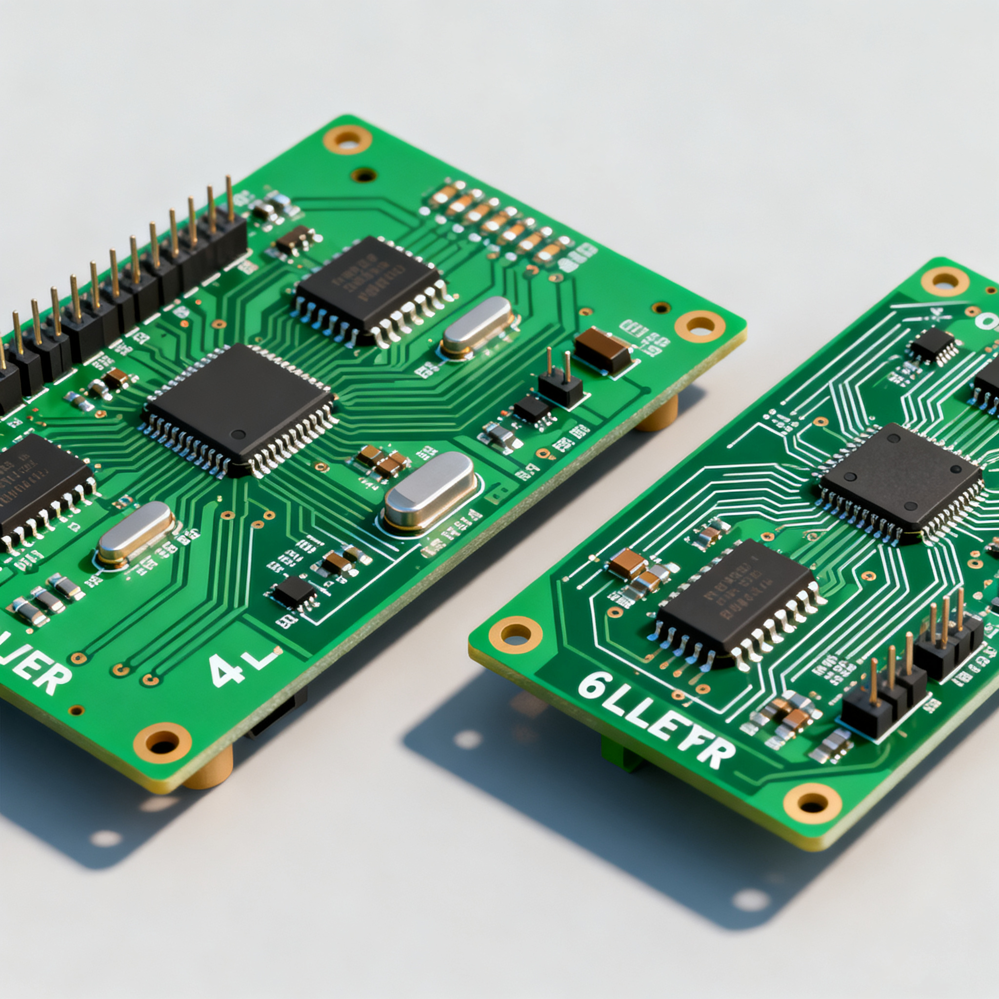
4-Layer vs. 6-Layer PCB Cost Comparison: A Buyer’s Selection Guide
Why Multilayer Cost Decisions Hit Harder in 2026 Choosing between a 4‑layer and a 6‑layer PCB stackup has never been a simple cost‑per‑square‑inch exercise, but the raw‑material turmoil that erupted t...
Why Multilayer Cost Decisions Hit Harder in 2026
Choosing between a 4‑layer and a 6‑layer PCB stackup has never been a simple cost‑per‑square‑inch exercise, but the raw‑material turmoil that erupted through 2025 is now spilling into every line of the bill of materials. What’s happening in 2026 is qualitatively different — resin systems, copper foil, glass fabrics and even solder mask are rising simultaneously, at a breadth that seasoned procurement leads compare to the 2021–2022 chip shortage. When every dollar of bare‑board cost multiplies across hundreds or thousands of panels, a layer‑count decision that used to be a design‑team technical vote now lands squarely on the CFO’s radar.
Skimping on layers to meet a unit‑price target looks attractive on paper, but the hidden penalties — lower first‑pass yield, longer lead times that stall time‑to‑market, and re‑spin cycles when a 4‑layer board can’t close timing — can erase the up‑front savings before the first production run ships. This guide lays out the process mechanics, real yield data, and volume thresholds so you can defend a stackup choice with numbers, not hunches.
What Makes a 6‑Layer Board 65% More Expensive Than a 4‑Layer
The headline number that keeps circulating — a 65% cost step from 4 to 6 layers on standard FR‑4 — isn’t a rough estimate; it’s an empirical average across mid‑volume orders tracked by fabricators. But that percentage doesn’t come from extra copper alone. The real driver is the second lamination press cycle. A 4‑layer board is produced in a single lamination step: the core, prepreg, and outer foils are stacked and pressed together. A 6‑layer board requires building the innermost core first, curing it, then running a second press to bond the outer signal layers. Each lamination cycle introduces fresh opportunities for warping, delamination and misregistration, and the overhead of that second press — time, energy, operator attention, and elevated scrap — compounds across the order.
The impact on manufacturing yield is immediate and measurable. Four‑layer boards typically achieve 97–98% first‑pass yield; six‑layer designs drop to 94–96%. That 2–4‑point gap means more panels enter rework or are scrapped outright, and every scrapped panel still carries the cost of the laminate, dry film, and all previous processing steps. Add the fact that fabrication lead time balloons by 24 to 48 hours — and in some shops from 3–5 days to 10–15 days — and the 65% premium starts to look more like a floor than a ceiling. The table below breaks the cost drivers into the variables that fabricators actually use when quoting.
| Cost Driver | 4‑Layer Board (FR‑4, ENIG, 1.6 mm) | 6‑Layer Board (FR‑4, ENIG, 1.6 mm) | Why It Matters for Your Quote |
|---|---|---|---|
| Lamination press cycles | 1 | 2 | Second press doubles lamination labour, utility cost and queue time; it also raises the chance of resin‑flow anomalies. |
| Typical first‑pass yield (medium complexity) | 97–98% | 94–96% | Lower yield increases the per‑board price because the shop builds redundancy into the panel count or passes scrap cost to you. |
| Inner‑layer registration tolerance | ±75 µm typical | ±50 µm achievable, but tighter control demands slower processing | Holding ±50 µm requires sequenced lay‑up, special pinning and intermediate X‑ray checks — all billable steps. |
| Material consumed (copper + prepreg) | ~2× core + 2× prepreg sheets | ~3× core + 4× prepreg sheets | Raw laminate cost rises by 40–50% before any processing; copper foil premiums push it higher when ½‑oz or thinner copper is specified for impedance control. |
| Prototype lead time (standard spec) | 3–5 working days | 6–10 working days; complex stackups can touch 15 days | Every extra day of fab time delays your bring‑up, which can be far costlier than the PCB itself in a time‑sensitive programme. |
| Impedance testing | One coupon strip (top/bottom) | Coupons on multiple signal layers; often requires TDR on 2–3 internal pairs | Test time and fixture cost multiply; some shops charge a flat fee per impedance‑controlled net, making a 6‑layer design more expensive to validate. |
| Typical cost delta (mid‑volume, no exotic materials) | Baseline 1.0× | 1.6–1.7× (65% premium) | At prototyping volumes this delta can widen; above 1 000 units it narrows slightly as fixed engineering and tooling amortize over more boards. |
The numbers don’t exist in a vacuum. FR‑4 is still the cost baseline for the vast majority of designs, but even on this mainstream material the lamination‑cycle overhead and yield gap produce the 65% jump. If your stackup requires a low‑loss laminate — Megtron 6, Rogers 4000‑series, or Isola I‑Speed — the absolute cost goes up further, but the percentage gap between 4 and 6 layers often holds because the extra lamination step remains a fixed process cost that doesn’t scale down with material choice.
4‑Layer vs. 6‑Layer: Stackup, Performance, and Lead‑Time Trade‑Offs at a Glance
A standard 4‑layer PCB delivers two external routing layers and two internal planes (usually power and ground), while a 6‑layer board adds two internal signal or plane layers, giving you the freedom to segregate high‑speed pairs, place continuous ground references directly under every signal trace, and dramatically reduce loop areas for EMI‑sensitive circuitry. The trade‑offs, however, are not limited to money. The table below summarises the head‑to‑head differences that purchasing teams and layout engineers alike need to see before committing a Gerber package.
| Comparison Metric | 4‑Layer Stackup (Signal‑GND‑PWR‑Signal) | 6‑Layer Stackup (Sig‑GND‑Sig‑Sig‑PWR‑Sig, typical) | Selection Criterion & Failure Boundary |
|---|---|---|---|
| Internal routing layers | None; all routing on outer layers | 2 internal Stripline or plane layers | If your design has >150 nets or multiple DDR interfaces, 4 layers quickly runs out of dog‑bone real estate. |
| Controlled impedance capability | Microstrip only; single‑ended 50‑Ω and differential 100‑Ω achievable with careful prepreg selection | Both Microstrip and Stripline; top‑bottom plus internal Stripline pairs with dual ground references | Stripline gives 6–10 dB better far‑field EMI suppression, often the difference between passing & failing radiated emissions on first sweep. |
| BGA support (0.8–1.0 mm pitch) | Struggles with >3 BGAs under 1.0 mm pitch; fan‑out vias consume all routing channels | Comfortably supports 4–6 BGAs; internal layers absorb escape routing without breaking plane continuity | More than three BGAs with sub‑1.0 mm pitch on a 4‑layer board guarantees routing bottlenecks and manufacturing defects. |
| EMI / EMC margin | Ground‑referenced outer traces; return path discontinuities when signals switch layers | Dedicated ground planes adjacent to every signal layer; continuous return paths that shrink loop area | If your product must meet CISPR 22/32 Class B, 6 layers often provide 8–12 dB extra margin over a 4‑layer design with identical layout rules. |
| Lead time (prototype, quick‑turn) | 3–5 working days | 6–10 working days; high‑layer‑count qualification can push to 15 days | 3–5 days for a 2‑layer board can become 10–15 days for a 6‑layer design; factor this delta into your NPI schedule. |
| Typical cost premium (FR‑4, 1 000 pcs) | 1.0× | 1.60–1.70× | Cost gap narrows slightly above 5 000 pcs but rarely falls below 1.45× due to persistent lamination‑cycle expenses. |
Readers considering a jump beyond 6 layers will face a different set of trade‑offs. No interface standard mandates 8 layers — the decision hinges on routing density, the number of high‑speed nets, and EMC margin. For designs that are already pushing the limits of a 4‑layer board, moving to 6 layers is often the smallest‑cost step that unlocks clean routing; the comparison above makes it clear that the technical headroom is substantial.
When to Fight for 4 Layers — and When 6 Layers Are Non‑Negotiable
Layer‑count choices are not one‑size‑fits‑all; they live or die by the specific electrical and mechanical constraints of your design. The next time you face pressure from the project office to save money, use the following evidence‑based decision rules to argue for — or against — the extra layers.
Fight for 4 layers when:
- Impedance targets can be met with a single‑ended Microstrip. One design team saved 40% versus a 6‑layer quote by placing a ground pour directly under a 50‑Ω antenna trace and adjusting the prepreg to 3.5 mil (<0.09 mm) dielectric height. A well‑tuned 4‑layer stackup often delivers antenna return loss better than –15 dB, eliminating the need for inner Stripline layers.
- Your BGA count is ≤3 and all pitches are ≥1.0 mm. At 1.0 mm pitch, a standard 0.2/0.4 mm via‑in‑pad fan‑out leaves enough space for two traces between vias on outer layers, which is usually sufficient for moderate pin‑count devices. Once you exceed three BGAs, the routing channels jam.
- Board real estate is generous. If the form factor allows 10–15% extra area, you can spread components, reduce crosstalk through physical separation, and avoid the need for internal shielding planes that a 6‑layer board would provide.
- Production volume is below 100 pieces and unit BOM cost is the sole selection driver. At prototype and low‑volume quantities, the 65% premium on a 6‑layer board is fully realised; the amortisation of fixed tooling, set‑up and test fixtures over a handful of boards yields no relief.
Accept 6 layers as non‑negotiable when:
- You have more than three BGAs with pitch ≤0.8 mm. Any design exceeding three BGAs under 1.0 mm pitch virtually guarantees routing bottlenecks and manufacturing defects on a 4‑layer board; via‑in‑pad and blind/buried via strategies simply eat up too many signal channels.
- EMC pre‑compliance scanning shows marginal headroom. If your product is already required to pass radiated emissions with 3 dB margin at a certified lab, the 6‑layer stackup with adjacent ground planes offers a cheaper insurance policy than multiple board spins — the extra layer cost is often recouped by avoiding a single re‑design and test cycle.
- High‑speed interfaces (USB 3.x, PCIe Gen3/4, DDR4) exceed three differential pairs. Crosstalk between tightly packed pairs on a 4‑layer board can easily violate a –30 dB NEXT spec; internal Stripline routing with solid ground planes cures this without resorting to exotic materials.
- Long‑term reliability demands it. In industrial or automotive environments where vibration and thermal cycling are routine, a 6‑layer board’s symmetrical stackup reduces warpage and improves plated‑through‑hole reliability over the product lifetime.
The decision matrix below maps real design scenarios to layer‑count recommendations, incorporating yield, cost, and schedule considerations.
| Design Scenario | 4‑Layer Feasibility | 6‑Layer Justification | Actionable Advice |
|---|---|---|---|
| Simple MCU + 2 BGAs (1.0 mm pitch), low‑speed peripherals | High; outer routing is ample | Overkill — cost and lead time penalty with no electrical benefit | Stay on 4 layers; invest PCB savings into better passive components. |
| IoT gateway with 50‑Ω antenna, one BGA SoC | High, if prepreg is adjusted to 3.5‑4 mil | Only if the SoC has a large ball matrix and demands Stripline escape | Request a stackup from your fab with controlled‑dielectric prepreg; you can hit return loss targets on 4 layers. |
| Medical wearable with 4 BGAs (0.8 mm), DDR4, and tight form factor | Marginal; routing channels will cramp | 6 layers become the cost‑effective path to avoid multiple layout iterations | Begin layout evaluation in 6 layers; the board area saved often offsets the layer premium. |
| Automotive camera module (MIPI CSI‑2, PoC, <40×40 mm board) | Feasible with Microstrip, but EMI from coaxial power may couple | Provides isolated Stripline for MIPI lanes and continuous ground, reducing radiated noise | Run parallel 4‑ and 6‑layer quotes; the per‑board delta in volume may be under 20% if panel utilisation improves in 6‑layer stack. |
| Production ramp from 500 to 5 000 units, tight BOM ceiling | Preferred; 65% premium on 5 000 boards is painful | Worth it if field reliability data shows that 4‑layer yields are causing latent failures | Scale the risk: the yield gap of 2–4% can erase a significant portion of the perceived savings. |
Tip: Always ask your fabricator for a panel‑utilisation analysis with both layer counts. On compact boards, the 6‑layer stackup may allow a smaller board outline, increasing the number of circuits per panel and shrinking the net‑per‑board premium from 65% to perhaps 30–40%.
Cost‑Critical Questions Engineers Ask Before Committing Layers
Q: Can I achieve 50‑Ω impedance and low EMI on a 4‑layer board instead of paying for 6 layers?
Often yes. By placing a continuous ground pour directly beneath the critical trace and tuning the prepreg thickness — typically 3.5 to 4 mil for FR‑4 — you can hit 50‑Ω single‑ended impedance without inner Stripline layers. One design team saved 40% versus a 6‑layer quote by optimising a 4‑layer stackup for a 50‑Ω antenna feed. That said, if your product must pass stringent radiated emissions limits (CISPR 32 Class B) and the layout is dense, a 6‑layer board’s dual solid ground planes provide a passive shield that is difficult to replicate on 4 layers. Start by generating a stackup table from your fabricator that confirms the prepreg resin content, then simulate the impedance in a field solver before locking the layer count.
Q: At what production volume does the 6‑layer per‑board premium really shrink?
At prototype quantities (5–100 pieces), the 65% premium is almost entirely process and material driven, with negligible relief from amortisation. Once you move into 1 000‑piece runs, fixed charges — CAM engineering, test fixtures, impedance coupon tooling — are spread across more units, and the delta may soften to 55–60%. Above 5 000 pieces, panel‑level costing starts to dominate, and the gap can tighten to roughly 45–55%, assuming the same board outline. However, because the second lamination cycle remains a fixed physical step, the premium never falls below approximately 40% on standard FR‑4. Always request parallel quotes for both layer counts at your projected run size; the exact gap depends on the fabricator’s panel layout and current material pricing.
Q: What is the single biggest hidden cost of moving to 6 layers?
The drop in first‑pass yield. A 4‑layer board yields 97–98% on the first electrical test, whereas a 6‑layer board drops to 94–96%. On a 500‑board order, that 2–4% yield loss corresponds to 10–20 extra scrap panels, each of which has already consumed all preceding process steps — dry‑film lamination, imaging, etching, AOI, oxide treatment, and press. Your fabricator prices this risk into the quote, so even if they don’t line‑item “yield contingency,” it’s baked into the per‑board cost difference. For high‑reliability designs where every panel is X‑rayed or cross‑sectioned, the cost impact is even larger.
Q: How much extra lead time does a 6‑layer board add over 4‑layer?
Typically 24 to 48 hours in a dedicated quick‑turn facility, purely due to the second lamination and the extra handling steps (post‑press baking, registration verification, and possibly a second drilling cycle if buried vias are used). That translates to a standard 4‑layer turnaround of 3–5 days stretching to 6–10 days for a 6‑layer board. When a design uses high‑Tg laminates, sequential lamination of blind/buried vias, or >2 oz inner‑layer copper, the lead‑time penalty can reach 10–15 days. For a product launch, that extra week can mean the difference between a smooth alpha build and a missed trade‑show deadline, so evaluate schedule risk alongside the fabrication quote.
Q: Can I use a premium material like Megtron 6 on a 4‑layer board to avoid moving to 6 layers?
It’s a legitimate trade‑off but not a universal silver bullet. Megtron 6 (Panasonic’s low‑Dk/low‑Df laminate) provides flatter insertion loss at GHz frequencies, which may let you run longer traces or thinner dielectrics while staying on 4 layers. The cost comparison, however, depends on your specific trace lengths and the volume of the order. On a small board with a handful of 12‑cm differential pairs, 4‑layer Megtron 6 can be cheaper than 6‑layer standard FR‑4 because you’re paying the material up‑charge but saving a whole lamination cycle. On a large board with many long traces, the square‑inch cost of the premium laminate can exceed the 6‑layer FR‑4 alternative. Always run parallel quotes that explicitly state the laminate brand, thickness, and copper weight.
Q: How do I request parallel quotes for 4- and 6‑layer boards so I can compare apples to apples?
Send your fabricator the same Gerber file and a clear stackup specification for both layer counts. Specify the identical material system (e.g., “Shengyi S1000‑2M FR‑4, Tg170, 4‑mil core”), copper weights, surface finish (ENIG or immersion tin), minimum trace/space, and target impedance. Ask them to quote the bare‑board price as a separate line from tooling, test fixturing, and shipping. State the exact volume — prototype qty 50, production qty 1 000, and an annual volume projection if you have it. A good supplier will return a side‑by‑side breakdown that makes the delta transparent. Expect the 6‑layer version to land 40–65% higher as a starting point, then negotiate based on the total spend. For a rapid sanity check, many online calculators give a baseline, but the live quotes from your chosen vendor are the only numbers that matter when you’re signing off a purchase order.
Key Takeaway: The 65% 6‑layer premium is real, but it’s not an iron law. Smart stackup tuning, panel‑utilisation analysis, and honest assessment of BGA density and EMI margin can shift the equation. At every volume, demand parallel quotes and total‑cost‑of‑ownership thinking — including the price of a re‑spin if the 4‑layer board can’t pass EMC or fit all signals. When your design reaches the point where the 4‑layer board is bleeding time-to-market and yield, the 6‑layer premium becomes cheap insurance.
Once your layer count is locked, the next critical step is assembly. NovaPCBA’s SMT lines handle fine‑pitch BGAs, impedance‑controlled boards, and mixed‑technology builds with inline AOI and X‑ray verification. Get a combined fabrication‑and‑assembly quote at novapcba.com and shorten your path from Gerber to tested product.