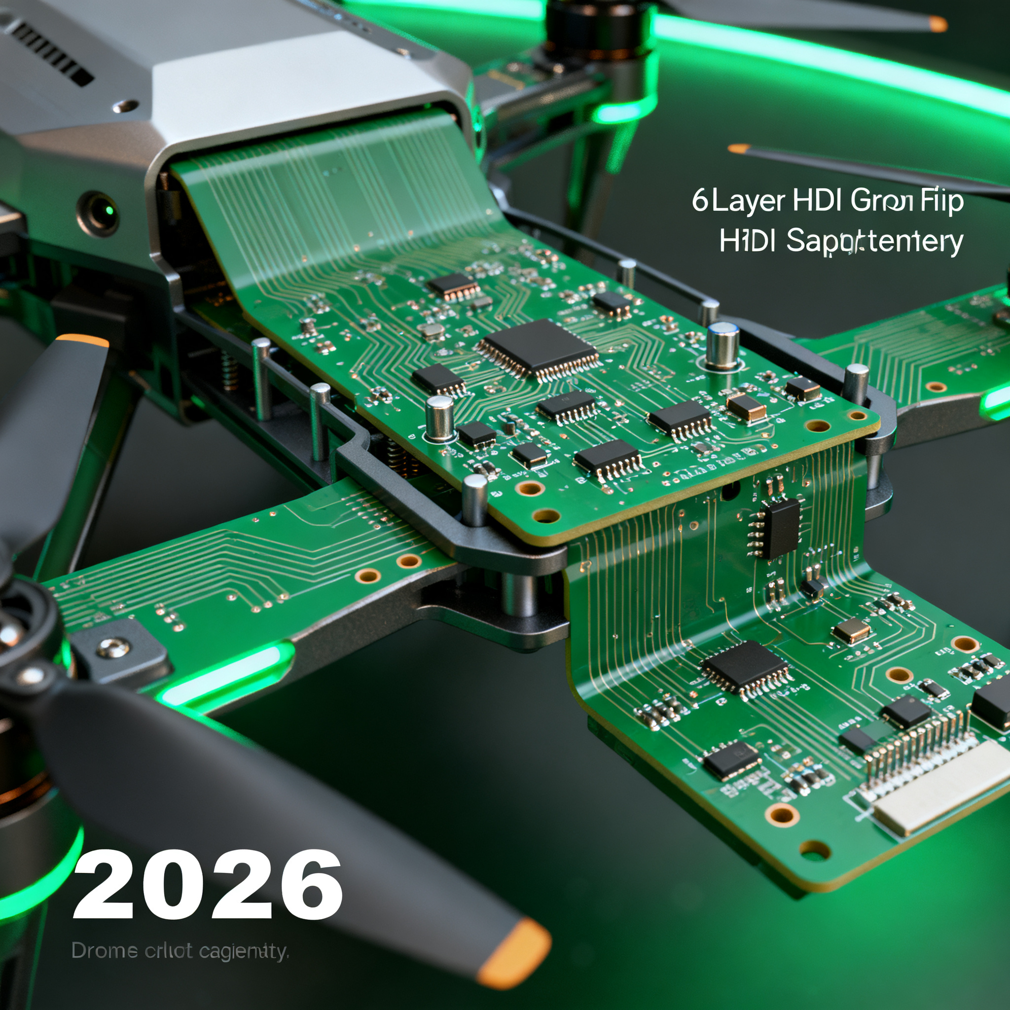
2026 Drone PCB Assembly Best Practices: How to Specify 6-Layer HDI Rigid-Flex Boards for Lightweight, High-Reliability UAVs
When Constant Vibration, Thermal Stress, and Weight Constraints Ground Drone Electronics Drone electronics fail differently than most other electronic systems. Between constant vibration, rapid thrott...
When Constant Vibration, Thermal Stress, and Weight Constraints Ground Drone Electronics
Drone electronics fail differently than most other electronic systems. Between constant vibration, rapid throttle changes, outdoor exposure, and compact high-power layouts, UAV circuit boards operate under continuous mechanical, thermal, and electrical stress — a combination that conventional rigid PCB designs were never engineered to withstand. AdvancedPCB catalogues the most common failure modes: connector fatigue from persistent vibration, pad cratering under shock loads, and delamination caused by thermal cycling between high-power motor drives and cold ambient air. When a drone drops from 120 meters because a solder joint fractured, the root cause is almost always a PCB that was not specified for the environment it actually flew in.
The problem compounds as drones get smaller and lighter. Foldable arms, gimbal-mounted cameras, and conformal airframes demand circuit boards that bend, fold, and conform to three-dimensional packaging envelopes — without adding the weight of connectors, ribbon cables, and mechanical fasteners. PCBSync explains that rigid-flex technology combines stiff sections for component mounting with flexible sections for connections, eliminating connectors entirely while enabling complex 3D packaging. FS Circuits describes rigid-flex as a hybrid technology that unites rigid and flexible circuit components into a single integrated assembly — one that reduces weight, simplifies assembly, and eliminates the failure-prone interconnects that plague conventional drone builds.
For 2026 drone programs — whether you are engineering a sub-250-gram FPV quad, a commercial delivery hexacopter, or a military-grade ISR platform — the specification conversation has shifted. AdvancedPCB notes that a drone PCB is designed and manufactured to operate reliably in an environment that combines mechanical stress, power density, and wireless communication challenges. A 6-layer HDI rigid-flex board is not a premium upgrade; it is the baseline architecture that makes lightweight, high-reliability UAVs physically possible. This article provides the best practices for specifying that board — from stackup design and material selection to bend radius rules and supplier qualification — so your next drone build flies longer, survives harder, and avoids the ground.
How 6-Layer HDI Rigid-Flex Boards Stack Up: Layer Count, Stackup Decisions, and IPC 2226/6012 Compliance
Six layers is the sweet spot for modern drone flight controllers, gimbal stabilizers, and integrated RF-digital boards. Four layers often cannot provide adequate isolation between high-speed digital traces and sensitive RF front-ends. Eight layers add mass, cost, and fabrication complexity that rarely justify the incremental signal integrity improvement for all but the most demanding radar or SIGINT payloads. Six layers give you enough real estate to dedicate entire planes to ground and power, isolate RF on a low-loss dielectric, and route differential pairs with controlled impedance — all within a rigid-flex architecture that folds into your airframe.
The typical 6-layer HDI rigid-flex stackup for a drone application uses rigid outer layers for surface-mount components and antennas, and flexible polyimide inner layers for the interconnects that bridge the rigid sections. Aivon provides detailed design rules for HDI flex applications, including microvia-in-pad design, material selection, and bend radius guidelines. AllPCB emphasizes that HDI PCB compliance requires meeting IPC 2226 and IPC 6012 standards to ensure reliable performance in high-density designs. The table below maps a proven 6-layer rigid-flex stackup that balances RF performance, digital routing density, and mechanical flexibility.
| Layer | Material | Function | Key Design Notes |
|---|---|---|---|
| L1 (Top) | Rogers 4350B (0.254 mm) | RF antenna / GPS patch / high-speed digital | Low Dk (3.48) at 10 GHz; maintain 50 Ω controlled impedance; microvia-in-pad to L2 |
| L2 | FR4 (0.18 mm prepreg) | Continuous ground plane | Uninterrupted reference for L1 RF traces; no splits under antenna region |
| L3 | Polyimide flex core (0.05 mm) | Flex signal layer 1 (differential pairs, SPI, I2C) | Adhesiveless polyimide; 100 µm trace width for 100 Ω differential; bend region only |
| L4 | Polyimide flex core (0.05 mm) | Flex power distribution | Wide copper pours for ESC power returns; hatched ground for flexibility |
| L5 | FR4 (0.18 mm prepreg) | Continuous ground plane | Reference for L6 digital; stitch vias along board perimeter |
| L6 (Bottom) | FR4 (0.254 mm) | Digital / power management / IMU | BGA breakout for IMU and MCU; teardrop pads on all flex-adjacent vias |
This stackup uses a 2+2+2 construction: two rigid layers on top, two flex layers in the core, and two rigid layers on the bottom. The rigid-to-flex transition zones are the most critical regions of the board. Aivon recommends a minimum bend radius of 1 mm for polyimide flex cores and advises staggering the rigid-to-flex boundary so that no single plane carries all the mechanical stress at the transition. IPC 2226 governs the design of HDI boards, and IPC 6012 defines the performance and acceptance criteria for rigid boards — but for rigid-flex, you must also comply with IPC 6013, which addresses the unique qualification and performance requirements of flexible and rigid-flex printed boards.
Tip: When specifying your 6-layer HDI rigid-flex board, explicitly call out IPC 6013 Class 3 on the fabrication drawing and require cross-sectional micrographs at the rigid-flex transition. This single requirement weeds out manufacturers who lack genuine rigid-flex expertise.
Hybrid Material Selection: Comparing Rogers, FR4, and Polyimide in a Single Stackup to Balance Cost and RF Performance
Material selection for drone rigid-flex boards is fundamentally an exercise in managing trade-offs. Rogers laminates deliver exceptional RF performance — low dielectric loss, stable Dk across temperature, and well-characterized behavior at GHz frequencies — but PCBSync reports that Rogers materials cost 5 to 10 times more than FR4. No commercial drone program can afford to build an entire 6-layer board from Rogers. The industry standard is the hybrid stackup: Rogers for the antenna layer, FR4 for the other rigid layers, and polyimide for the flex core. This approach places the premium material precisely where it adds value — in the RF signal path — while using cost-effective FR4 everywhere else.
AdvancedPCB compares rigid-flex against rigid-plus-connectors and finds that rigid-flex is typically the most expensive option in a direct material-cost comparison. But the system-level economics tell a different story: the added cost is often justified when the benefits of weight reduction, improved reliability, and compact packaging are factored in. A rigid-flex board eliminates multiple connectors, reduces assembly labor, and cuts the weight of cabling and hardware — all of which translate directly to longer flight times and fewer field failures. PCBA Store confirms that weight affects flight length, payload capacity, and general efficiency directly, and that lightweight designs using HDI, rigid-flex, and smaller components increase operational time.
The comparison table below captures the material and cost trade-offs engineers face when specifying a hybrid rigid-flex stackup for drone applications.
| Comparison Metric | Rogers 4350B (RF Layer) | FR4 (Digital / Power Layers) | Polyimide (Flex Core) | Selection Criteria & Failure Boundary |
|---|---|---|---|---|
| Dk @ 10 GHz | 3.48 ± 0.05 | 4.2–4.6 (uncontrolled) | 3.4–3.5 | Rogers required for antenna layers; FR4 Dk variation causes impedance mismatch above 2 GHz |
| Dissipation Factor (Df) | 0.0037 | 0.02–0.025 | 0.002–0.005 | Df above 0.01 on RF layers causes unacceptable insertion loss in GPS and video links |
| Relative Cost Factor | 5–10× | 1× (baseline) | 3–5× | Hybrid stackup keeps total material cost at 1.5–2.5× all-FR4; use Rogers only on L1 |
| Tg (Glass Transition) | >280°C | 130–170°C (standard) | >250°C | FR4 Tg must exceed peak reflow + 25°C; specify high-Tg FR4 (170°C) for lead-free assembly |
| Flex Cycles to Failure | N/A (rigid only) | N/A (rigid only) | >100,000 at 1 mm bend radius | Polyimide flex life depends on bend radius, copper grain direction, and coverlay adhesion |
| CTE (X/Y, ppm/°C) | 14–16 | 14–17 | 12–20 | CTE mismatch between rigid and flex layers causes delamination; match within 5 ppm/°C |
| Moisture Absorption (%) | 0.06 | 0.1–0.2 | 0.8–1.2 | Polyimide absorbs moisture; specify post-bake before assembly to prevent popcorning |
The cost comparison between rigid-flex and rigid-plus-connectors is not purely about the board fabrication price. AdvancedPCB notes that rigid-flex requires a manufacturer with specialized flex and rigid-flex experience — a qualification hurdle that limits the supplier pool and can increase per-unit costs. However, when you eliminate two or three board-to-board connectors, a dozen crimped cable assemblies, and the associated assembly labor, the total system cost often favors rigid-flex. For drones where every gram matters, the weight savings alone — typically 20 to 40 percent over a connectorized rigid design — make the decision straightforward.
On lead times: PCBA Store reports that normal lead time for custom drone PCB assembly is three to five business days after all parts arrive, with expedite options that drop to 24 or 48 hours for critical prototypes. Minimum order quantity is one board, though PCBA Store recommends ordering three to account for assembly trials and destructive testing. For a full 6-layer HDI rigid-flex prototype — fabrication plus assembly — plan on 10 to 15 working days from a qualified manufacturer, and verify that the shop has completed similar rigid-flex drone builds before committing to a schedule.
Specifying a 6-Layer HDI Rigid-Flex Board: Design Rules, Bend Radius, and Sourcing Pitfalls to Avoid
Specifying a rigid-flex board for a drone is not a simple extension of rigid PCB design. The flex sections introduce mechanical degrees of freedom that rigid board designers rarely consider — and getting them wrong produces failures that manifest only after the drone has been flying for weeks or months. Aivon provides detailed flexible circuit design rules, HDI bend radius guidelines, and material selection best practices that every engineer specifying a rigid-flex drone board should internalize. Below is a practical specification checklist that addresses the most common failure modes we see in production UAV builds.
- Define the minimum bend radius before routing a single trace. Aivon recommends a minimum bend radius of 1 mm for polyimide flex, but this is application-dependent. For dynamic flex applications — such as a foldable drone arm that cycles every flight — use a bend radius of at least 10× the flex thickness. For static bends (a one-time fold during assembly), 6× the flex thickness is acceptable. Specify the bend radius on the fabrication drawing and require the manufacturer to confirm it in the stackup report.
- Keep components and vias out of the bend zone. The flex region should be exclusively copper traces with coverlay. Placing a component or a plated via on or within 2 mm of the bend line creates a stress concentration that will crack the solder joint or the via barrel. Establish a clear "keep-out" zone on your layout and enforce it with a DRC rule.
- Use teardrop pads on all flex-adjacent vias and surface-mount pads. The transition from rigid to flex creates a mechanical discontinuity. Teardrop-shaped pad connections distribute stress over a larger area and reduce the risk of trace cracking at the pad interface. This is a trivial layout adjustment that prevents catastrophic failures.
- Enforce a symmetrical stackup. Asymmetric copper distribution between the top and bottom rigid sections causes warpage during lamination and reflow. The stackup must be balanced: if L1 has a 35 µm copper pour, L6 should have a matching copper weight and density. This is especially important for 6-layer boards where the flex core is thin and easily deformed by unbalanced rigid layers.
- Specify IPC Class 2 or 3 on the fabrication drawing. AllPCB recommends IPC 2226 and IPC 6012 compliance for HDI boards, and for mission-critical drones, Class 3 is the appropriate choice. Class 3 imposes tighter acceptance criteria for plating thickness, annular ring dimensions, and solder joint integrity — all of which directly affect field reliability in vibration-prone environments.
- Verify RoHS and REACH compliance for all materials. AllPCB's checklist also highlights that RoHS and REACH rules affect high-density board fabrication and can prevent assembly failures if non-compliant materials are inadvertently used. Specify RoHS-compliant laminates, surface finishes, and solder mask, and require a certificate of compliance from the manufacturer.
- Order at least three prototype boards, even if the MOQ is one. PCBA Store notes that minimum order quantity is one board, but recommends ordering three. Use one for functional validation, one for bend-cycle testing, and keep one as a golden reference. The cost of three prototypes is negligible compared to the cost of a field failure on a production drone fleet.
AdvancedPCB warns that rigid-flex requires a manufacturer with specialized flex and rigid-flex experience — not every PCB shop that can produce an 8-layer rigid board can handle a 6-layer HDI rigid-flex with embedded polyimide. The sourcing pitfalls are real: a manufacturer that lacks rigid-flex expertise may produce boards that pass electrical test but delaminate after 50 bend cycles or fail after the first thermal shock. The table below summarizes the key parameters to specify and verify when sourcing a 6-layer HDI rigid-flex drone board.
| Specification Parameter | Recommended Value | Verification Method | Why It Matters for Drones |
|---|---|---|---|
| Layer count | 6 (2 rigid + 2 flex + 2 rigid) | Cross-sectional micrograph in stackup report | Fewer layers sacrifice isolation; more layers add unnecessary weight |
| Flex core material | Adhesiveless polyimide, 50 µm | Material datasheet and C of C | Adhesiveless construction eliminates delamination risk at the flex-rigid interface |
| Minimum bend radius | 1 mm (static), 10× flex thickness (dynamic) | Bend test report per IPC-6013 | Underspecified bend radius causes trace cracking in foldable drone arms |
| HDI via type | Laser-drilled microvia (100 µm), via-in-pad on L1 | X-ray inspection of via fill | Microvias save space on dense flight controller layouts; poor fill causes voids |
| Surface finish | ENIG (electroless nickel immersion gold) | XRF thickness measurement | ENIG provides flat pads for fine-pitch BGAs and resists oxidation in humid environments |
| IPC classification | IPC-6013 Class 3 | Supplier audit and lot acceptance test report | Class 3 ensures plating integrity and annular ring requirements for high-reliability UAVs |
| Impedance control | 50 Ω single-ended, 100 Ω differential, ±10% | TDR coupon on panel | GPS, video, and telemetry links fail without controlled impedance on RF layers |
| RoHS / REACH compliance | Full compliance required | Supplier declaration and test reports | Non-compliant materials can block EU market access and cause reliability issues |
The specification document you send to the manufacturer should include every parameter in this table, plus a detailed stackup drawing, a flex bend area drawing with dimensions, and a note that cross-sectional micrographs are required at the rigid-flex transition. A manufacturer that questions these requirements or suggests substituting a simpler construction is not qualified for this build.
Rigid-Flex for UAVs: Questions Engineers and Buyers Ask Before Signing Off on a Build
After 15 years of specifying rigid-flex boards for aerospace, defense, and commercial drone programs, we have heard every question — and every objection. Below are the six questions that senior engineers and procurement leads consistently raise when evaluating a 6-layer HDI rigid-flex design for a new UAV program. Each answer is grounded in the research and field experience that inform this entire article.
Q: What real weight savings can I expect from a 6-layer HDI rigid-flex board versus a rigid board with connectors?
Rigid-flex eliminates connectors, cabling, and the associated mounting hardware — all of which contribute significant mass in a drone that may weigh only 250 grams fully assembled. PCBSync explains that rigid-flex combines stiff sections for component mounting with flexible sections for connections, eliminating connectors entirely while reducing weight and failure points. PCBA Store notes that lightweight designs with HDI, rigid-flex, and smaller components directly increase operation time. In typical flight controller or gimbal assemblies, the weight reduction is 20 to 40 percent compared to an equivalent rigid board with board-to-board connectors and wire harnesses. For a drone that flies for 25 minutes on a rigid design, that weight savings can translate to an additional 3 to 7 minutes of flight time — or the ability to carry a larger payload.
Q: How many bend cycles can a typical rigid-flex drone interconnect withstand?
A properly designed polyimide flex with a 1 mm minimum bend radius can survive hundreds of thousands of dynamic flex cycles. Aivon details bend radius guidelines and material selection in its HDI flex design guide, and IPC-6013 defines the formal bend cycle requirements for qualification. The key factors that determine flex life are bend radius, copper grain direction (rolled annealed copper is preferred for dynamic flex), and the quality of the coverlay adhesion. For a foldable drone arm that cycles once per flight, even a conservative design with a 2 mm bend radius will outlast the rest of the airframe. The failure mode is not fatigue in the copper itself but rather delamination at the coverlay interface — which is why specifying adhesiveless polyimide and requiring a bend-test report from the manufacturer are essential.
Q: What IPC class should I specify for a drone flight controller board?
Drone flight controllers typically require IPC Class 2 or Class 3, depending on mission criticality. AllPCB references IPC 2226 and 6012 for HDI compliance, and AdvancedPCB explains why outdoor and vibration-prone environments demand higher class requirements. Class 2 is acceptable for consumer drones where a failure means a lost toy. Class 3 is recommended for any UAV that flies over people, carries valuable payloads, or operates in commercial airspace. Class 3 imposes tighter acceptance criteria for plating thickness (minimum 20 µm in through-holes), annular ring dimensions (minimum 25 µm external), and solder joint voiding. These are not arbitrary quality metrics — they are the difference between a board that passes initial test and a board that survives 500 flight hours.
Q: Can I use a hybrid Rogers/FR4 stackup without signal integrity issues?
Yes, hybrid Rogers/FR4 stackups are the industry standard for drone RF-digital boards. PCBSync confirms that most designs use hybrid stackups: Rogers for the antenna layer, FR4 for everything else. The key to signal integrity is to run impedance simulations (using a tool like Polar Si9000 or Ansys HFSS) with the actual material properties, and to maintain consistent reference planes across the material transition. The Rogers layer is placed only where it is needed — typically on L1 for the antenna feed network and RF front-end — and the transition to FR4 on L2 is managed by ensuring that the ground plane is continuous and uninterrupted. The impedance difference between Rogers (Dk 3.48) and FR4 (Dk ~4.3) means that traces crossing the material boundary must be simulated carefully, but in practice, the RF traces are confined entirely to the Rogers layer, and the transition is only relevant for vias that connect L1 to the inner layers.
Q: What is the typical lead time for a 6-layer HDI rigid-flex prototype?
After all parts are received, custom drone PCB assembly usually takes 3 to 5 business days, with expedite options of 24 or 48 hours for critical prototypes, according to PCBA Store. The full lead time for fabrication and assembly of a 6-layer HDI rigid-flex prototype is typically 10 to 15 working days from a qualified manufacturer, but this varies significantly based on the shop's rigid-flex expertise and current workload. Plan for 15 working days as a realistic baseline, and do not compress the schedule at the expense of cross-sectional micrograph review or bend-test verification. A rushed prototype that fails in the field costs far more time than an extra week in fabrication.
Q: How do I verify that a manufacturer is qualified for rigid-flex drone PCBs?
Ask for evidence of IPC-6013 qualification, demonstrated experience with HDI rigid-flex builds of six or more layers, and a portfolio of drone or aerospace assemblies. AdvancedPCB warns that rigid-flex requires a manufacturer with specialized flex and rigid-flex experience — this is not a capability that every PCB shop possesses. AllPCB recommends checking for RoHS and REACH compliance and verifying IPC 2226 adherence. Request a sample stackup from a previous rigid-flex drone build, ask for a bend-test report that demonstrates flex cycle life, and — if the program volume justifies it — conduct an on-site audit of the manufacturer's rigid-flex production line. A manufacturer that hesitates to provide these artifacts is not qualified for your build.
At NovaPCBA, we specialize in 6-layer HDI rigid-flex assembly for drone, aerospace, and medical applications where reliability is non-negotiable. Our engineering team reviews every rigid-flex stackup before fabrication begins, verifies bend-radius compliance against IPC-6013, and provides full cross-sectional micrograph and bend-test reports as standard deliverables. Whether you are prototyping a new flight controller or scaling a production UAV program, the right manufacturing partner makes the difference between a board that works on the bench and a board that survives years of flight.
References & Further Reading
- 5 PCB Failures That Ground Drones, and How to Design Against Them | AdvancedPCB
- Drone PCBs: Requirements, Materials, Standards, and Design Priorities | AdvancedPCB
- Drone PCB Design: Complete Guide to Components, Layout & Manufacturing [2026] | PCBSync
- Professional Drone PCB Assembly Manufacturing Services | FS Circuits
- HDI PCB Design for Flex and Rigid Flex Applications | Aivon
- Navigating the Complexities of Drone Flight Control PCB Manufacturing | AllPCB
- Ultimate Guide to Drone PCB Optimizing Design & Manufacturing | PCBA Store
- How to Choose a Drone PCB Manufacturer | PCBA Store
- Drone PCBs: Materials Comparison | AdvancedPCB
- Guide to Drone PCBs: Optimizing Design & Manufacturing | ElePCB